Electrical Safety Testing and Measurement Detection for HVAC Systems: A Global Professional Guide
Electrical safety testing and measurement detection are non-negotiable components of professional HVAC installation and maintenance. Whether you're commissioning a new system, troubleshooting equipment failures, or conducting routine preventive maintenance, the ability to accurately measure electrical parameters directly impacts system reliability, personnel safety, and regulatory compliance. This guide provides HVAC contractors and installers with practical, data-driven protocols for electrical safety testing across global markets, integrating modern measurement tools and field-proven best practices.
Understanding Electrical Safety Testing in HVAC Applications
Electrical safety testing encompasses multiple measurement and detection disciplines that work together to verify system integrity. In HVAC applications, electrical testing typically involves three critical measurement domains: voltage detection, circuit continuity and resistance measurement, and thermal monitoring.
Voltage detection identifies the presence and magnitude of electrical potential in circuits before technicians make connections or perform service work. This is the first line of defense against electrical hazards. Modern measurement and detection tools use non-contact and direct-contact methods to identify live circuits safely. Non-contact voltage detectors operate by sensing electromagnetic fields without requiring physical circuit contact, reducing exposure risk during initial circuit assessment.
Multimeters extend voltage detection to include resistance (ohm) measurement, continuity testing, and current measurement across AC and DC circuits. These instruments are essential for diagnosing control circuit failures, verifying compressor motor windings, testing safety interlocks, and confirming proper ground continuity. Professional-grade digital multimeters provide accuracy ratings of ±0.5% to ±3.0% depending on the measurement range, critical for identifying marginal circuit conditions that could lead to nuisance shutdowns or component failure.
Thermal measurement through infrared detection and immersion thermometers allows technicians to monitor system operating temperatures, detect equipment overheating, and verify proper refrigerant charge indirectly through superheat and subcooling calculations. Temperature measurement accuracy directly correlates to diagnostic precision—a 2°C error in superheat measurement can lead to improper refrigerant charging, reducing system efficiency by 5-15% and accelerating compressor wear.
In global markets operating under diverse regulatory frameworks (ISO 13849-1 for safety-related control systems, IEC 61010 for electrical measurement equipment, and regional electrical codes), comprehensive electrical testing documentation protects both the contractor and end-customer by establishing verifiable system compliance at installation and throughout the service life.
Professional Measurement Tools for HVAC Electrical Safety
Selecting appropriate measurement instruments requires understanding both tool capabilities and application requirements. The foundation of electrical safety testing begins with voltage detection.
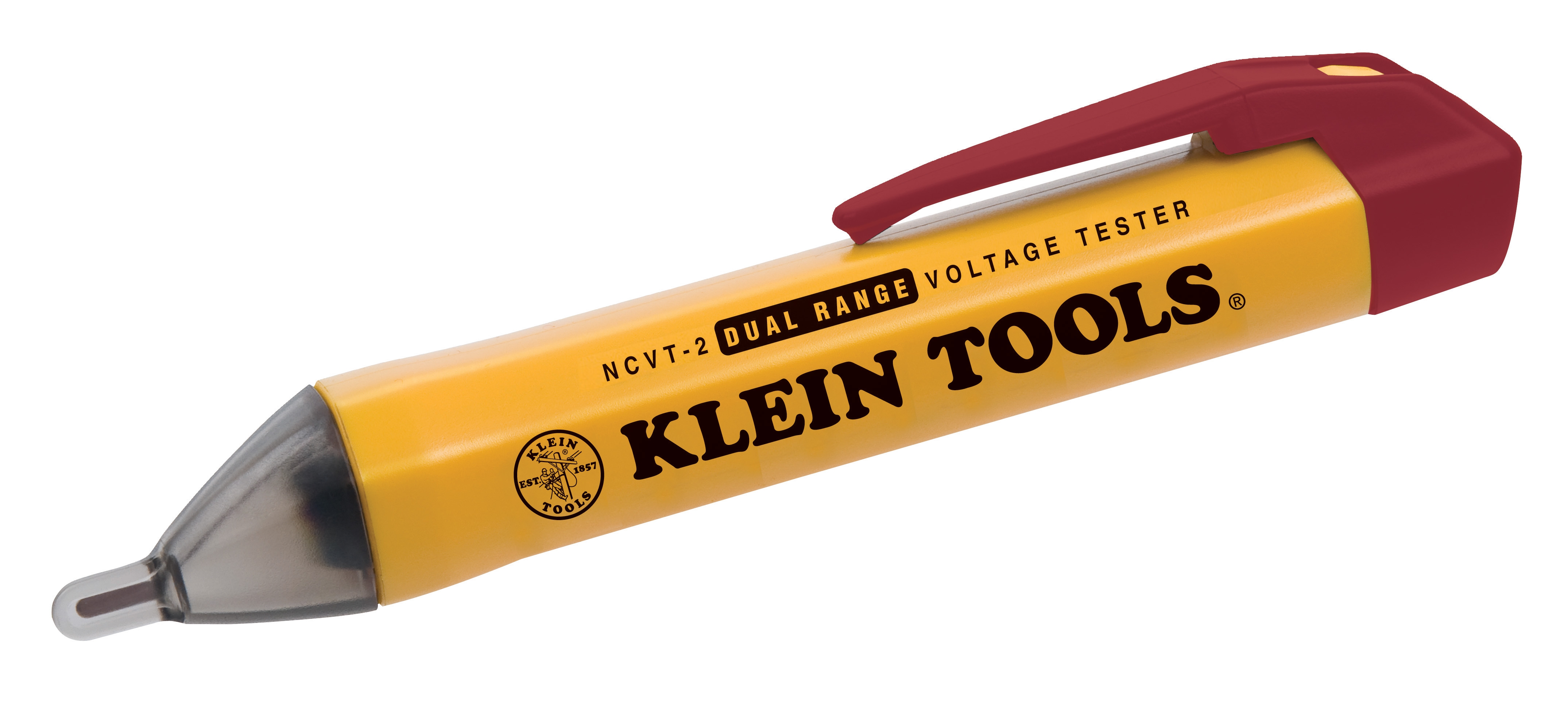
The CBM Non-Contact Voltage Detector represents modern non-contact technology, designed specifically for identifying live circuits without direct contact. This dual-range device operates in two sensitivity modes: a lower range suitable for standard household and light commercial circuits (100-120V AC nominal), and an extended range for detecting higher voltages in industrial panel installations. Non-contact detectors excel at the initial circuit survey phase, allowing rapid identification of energized circuits in crowded electrical panels where space constraints complicate traditional probe-based testing. The device features an audible indicator and visual LED confirmation, enabling hands-free operation in confined spaces.
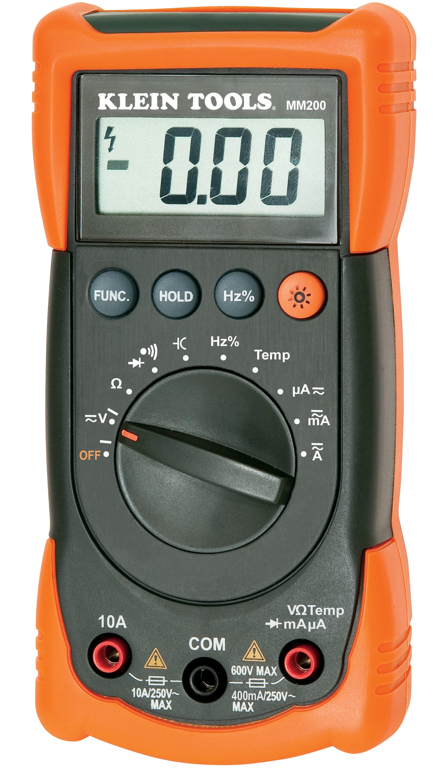
Once live circuits are identified and properly locked out/tagged out (LOTO), comprehensive circuit analysis requires a digital multimeter. The CBM Automatic Multimeter MM420 provides automatic range selection across voltage, resistance, and current measurements. Automatic ranging eliminates the common field error of selecting incorrect measurement ranges, which can damage analog meters or produce unreliable readings. The MM420 includes AC current measurement capability up to 400mA on low-current ranges, essential for verifying control circuit loads in 24-volt thermostat circuits and safety relay circuits. Digital display resolution of 0.1mV on DC voltage ranges enables detection of marginal voltage conditions that indicate failing components or loose connections.
For thermal diagnostics, the CBM Type K Thermocouple for Infrared Thermometer extends non-contact infrared measurement capabilities. Type K thermocouples measure from -40°C to +1000°C, encompassing both cryogenic refrigerant work and high-temperature furnace applications. The thermocouple design allows surface temperature measurement on moving components and in locations where contact thermometers cannot be safely positioned.
Pressure measurement diagnostics support electrical system testing indirectly. The CBM Glycerin Stainless Steel Pressure Gauge (D50, 0/+4 bar) and companion CBM Expansion Tank Inflator with Battery enable verification of heating system pressurization. Proper system pressure ensures that pressure relief devices function correctly and that electrical pressure switches activate at designed setpoints—critical for preventing electrical nuisance trips in hydronic heating systems integrated with HVAC installations.
Step-by-Step Electrical Safety Testing Protocol for HVAC Systems
Step 1: Pre-Test Equipment Verification
Before beginning any field measurement, verify that your test instruments themselves are functioning correctly. Test your non-contact voltage detector against a known live circuit (building wall outlet or disconnect switch in energized position). Verify multimeter battery condition by measuring a 1.5V reference battery. Document baseline readings. Defective test instruments introduce false negatives that compromise safety.
Step 2: Non-Contact Circuit Survey
Use the non-contact voltage detector to scan the entire electrical panel and circuit connections you will be working with. Move the detector probe slowly around circuit breakers, disconnects, and terminal connections. Mark any circuits showing voltage indication. This phase requires no lockout and identifies hazard zones before personnel begin detailed work.
Step 3: Lockout/Tagout Implementation
De-energize the circuits identified as live. Apply locks and warning tags to disconnect switches per OSHA 29 CFR 1910.147 (Global equivalents: PUWER 1998 UK, Work Health and Safety Act Australia). Verify lock operation by attempting to re-energize—the system should remain de-energized.
Step 4: Multi-Phase Voltage Verification
Using the multimeter set to AC voltage mode, verify that all circuit phases read 0V ±2V (approximately 0.5% of nominal voltage). Test across phase-to-ground and phase-to-neutral connections. This double-verification confirms that lockout was successful and the circuit remains de-energized throughout testing duration.
Step 5: Control Circuit and Component Testing
Measure voltage across safety interlocks, transformer secondary windings, and control relays to confirm proper operation under energized conditions (with appropriate personnel protection). Use the multimeter's resistance mode to test transformer secondary coils (expected impedance typically 10-100 ohms depending on transformer rating). Test compressor motor winding resistance—three-phase motors should show approximately equal resistance across all phase pairs (typically 5-15 ohms for single-phase motors, 2-10 ohms for three-phase units).
Step 6: Thermal Verification
Measure system operating temperatures at critical points: compressor discharge, evaporator outlet, and furnace heat exchanger surfaces. Document temperature readings for comparison against design specifications and future service records.
Best Practices for Electrical Measurement and Detection in HVAC Work
Document All Readings: Maintain field test logs recording voltage, resistance, current, and temperature measurements with timestamps and circuit identifications. These records provide baseline data for future troubleshooting and demonstrate compliance with equipment manufacturers' commissioning requirements and local electrical codes.
Understand Tool Accuracy Limitations: Non-contact detectors typically provide ±10% accuracy in voltage indication—they confirm presence or absence of voltage rather than precise voltage magnitude. Use direct-contact multimeters for specific voltage values. Multimeter accuracy varies by range; DC voltage measurements on 2V range provide 0.1V resolution, while 600V range provides 1V resolution. Select appropriate ranges for your measurement precision requirements.
Implement Temperature Compensation: Resistance and voltage measurements vary with temperature. Conduct critical resistance measurements (compressor winding tests, safety device continuity) at consistent ambient temperatures, ideally 20-25°C. Temperature variance of 10°C can introduce 0.3% to 0.5% error in resistance measurement.
Verify Ground Continuity Continuously: Measure equipment ground connections (equipment frame to building ground) with multimeter resistance mode. Ground impedance should be less than 1 ohm for proper safety device coordination. Poor grounding delays current flow during faults, preventing circuit breaker operation and creating extended shock hazard windows.
Maintain Calibration Records: Digital multimeters should be calibrated annually according to the manufacturer's specifications. Professional calibration services provide NIST-traceable certification documenting measurement accuracy. Calibration certificates provide legal protection in accident investigations and warranty disputes.
Integrating Measurement Data into System Commissioning
Electrical measurement and detection data form the foundation of system commissioning documentation. Combine voltage and current readings with pressure and temperature measurements to create comprehensive baseline records that define normal system operation. These baselines enable proactive fault detection during future service calls—a 15% increase in compressor motor current combined with elevated discharge temperature suggests motor bearing degradation before catastrophic failure occurs.
Document all measurement readings in equipment manufacturer commissioning forms and create digital archives accessible to service technicians on subsequent visits. Modern work management systems can correlate historical measurement trends, identifying degradation patterns that inform planned maintenance scheduling.
3G Electric provides comprehensive measurement and detection equipment specifically selected for HVAC professional use. Our team understands the measurement challenges contractors face across global markets with varying electrical standards and code requirements. Contact our technical support team to discuss your specific measurement and detection requirements, explore instrument specifications in detail, and access product documentation supporting your commissioning protocols. We partner with HVAC professionals to ensure you have accurate, reliable tools that enable safe, code-compliant installations and efficient troubleshooting throughout your service territories.