Understanding Controls & Safety in Vibration-Prone Environments
Controls & Safety systems protect industrial burner operations through integrated flame detection and signal amplification. In manufacturing facilities, process heating systems, and large-scale HVAC installations, mechanical vibration from adjacent equipment, blowers, and compressors creates an electromagnetic environment that challenges traditional control architectures. After 35+ years of distributing industrial equipment globally, 3G Electric recognizes that vibration resilience is not a luxury—it is a fundamental requirement for maintaining operational safety and uptime.
Flame detection amplifiers must distinguish between legitimate flame signals and electromagnetic noise induced by vibration. A poorly specified amplifier can trigger false shutdowns, interrupting production and creating safety hazards during restart sequences. Conversely, an amplifier that is too tolerant of noise risks missing genuine flame loss conditions. The solution lies in understanding how modern amplifiers achieve vibration tolerance through mechanical design, signal filtering, and response time optimization.
Mechanical Vibration Tolerance and Amplifier Architecture
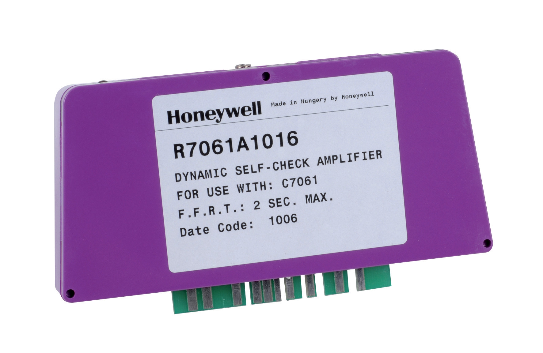
Industrial flame detector amplifiers like the Honeywell Amplifier R 7861 A 1026 are engineered to operate reliably in environments experiencing continuous vibration of 0.5 g or higher. To understand what this specification means, consider that 0.5 g continuous vibration is equivalent to the acceleration experienced by equipment mounted directly above high-speed rotating machinery. This is the typical environment in power generation plants, food processing facilities, and large commercial boiler rooms.
The mechanical resilience of modern amplifiers derives from three design principles:
- Potted Electronics: Internal components are encapsulated in vibration-damping epoxy resin, reducing stress on solder joints and wire connections. This potting also provides thermal stability across the operating range of -40°C to +60°C, protecting semiconductor performance in both arctic and tropical industrial environments.
- Reinforced PCB Mounting: Circuit boards are mounted on elastomeric isolators and secured with vibration-resistant fasteners. These isolators decouple the board from the housing, preventing mechanical transmission of vibration energy to sensitive components like operational amplifiers and logic circuits.
- Shielded Signal Pathways: Internal wiring for flame sensor inputs uses twisted, shielded pairs that minimize capacitive coupling of electromagnetic noise. This shielding is critical because flame detector sensors operate at microvolt levels, and ambient electromagnetic fields from welding equipment, motor drives, and radio transmitters can induce signals that rival the legitimate flame signal.
The Honeywell Cell C 7044 A 1006 ultraviolet flame detector generates a signal in the picoampere range when exposed to flame radiation. The amplifier must convert this minuscule signal into a logic-level output (typically 24 VDC) without amplifying vibration-induced noise. This is achieved through low-noise preamplification stages with gain settings optimized for the specific sensor type—a critical compatibility requirement often overlooked during system commissioning.
Signal Processing and Noise Discrimination Strategies
Modern flame detector amplifiers employ multiple filtering and decision-making strategies to distinguish flame signals from electrical noise:
Frequency Filtering: Flame signals occupy specific frequency bands depending on the combustion process and sensor type. Ultraviolet sensors respond to flame radiation flicker at frequencies between 4 Hz and 8 Hz for most hydrocarbon flames. The amplifier incorporates bandpass filters tuned to this frequency range, rejecting noise at power line frequencies (50/60 Hz), switching frequencies from power electronics (tens of kilohertz), and mechanical vibration harmonics (typically <15 Hz or >200 Hz depending on machinery type).
Response Time Windowing: Flame loss must be detected within 2–5 seconds depending on safety standards and equipment type. The amplifier's decision logic requires that the flame signal remain above threshold for a minimum duration (typically 1–2 seconds) before confirming flame presence. This windowing prevents single transient events (electromagnetic spikes) from triggering false confirmations. Conversely, when flame is lost, the amplifier initiates an immediate shutdown sequence without waiting for a confirmation window, because flame loss is a critical safety event that cannot tolerate delay.
Adaptive Threshold Management: Some advanced amplifiers monitor baseline electrical noise over time and automatically adjust detection thresholds to maintain a consistent signal-to-noise ratio. This is particularly valuable in facilities where new equipment is added or facility electrical infrastructure is upgraded, which can change the ambient noise floor.
The Honeywell R7861A 1026 amplifier incorporates these strategies while maintaining compatibility with standard ultraviolet and infrared flame detectors used across different burner types and fuel types (natural gas, propane, fuel oil, dual-fuel configurations).
Integration with Control Modules and Thermostat Systems
Flame detection amplifiers operate within a hierarchical control architecture. The amplifier's flame/no-flame output feeds into a burner control module—such as the Pactrol CSS01 12 control module—which orchestrates the entire burner startup and shutdown sequence.
A typical sequence works as follows:
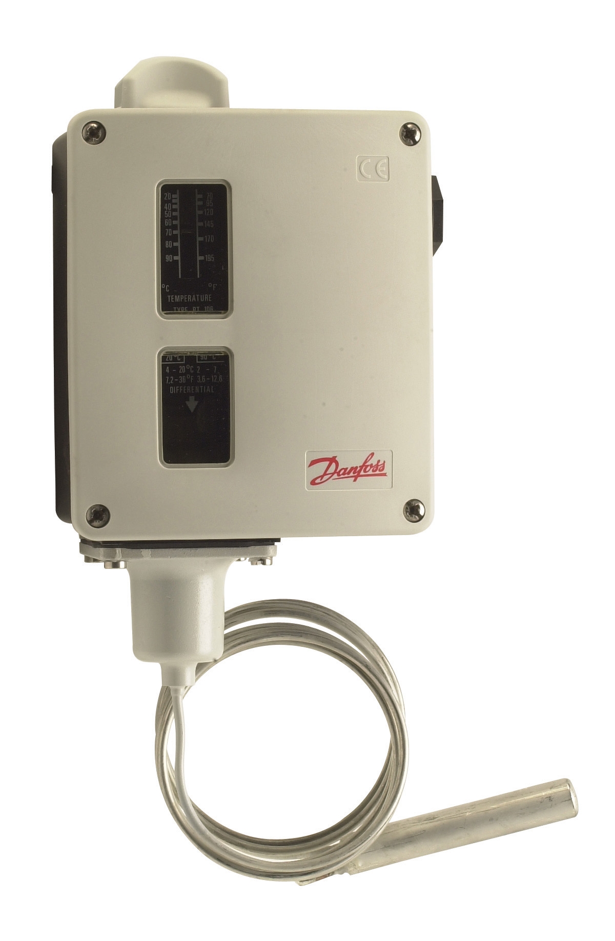
1. Startup Request: An external thermostat or process controller initiates startup by closing a 24 VDC circuit. The Danfoss RT 124 or Danfoss RT 107 thermostat continuously monitors setpoint, generating a call for heat when room or process temperature drops below setpoint.
2. Ignition Phase: The control module energizes the electronic spark generator and fuel solenoid valve. During the first 5 seconds, the igniter must prove that flame has been established. The flame detector amplifier monitors the ultraviolet or infrared sensor and reports flame presence to the control module.
3. Flame Confirmation: If the amplifier detects flame within the proving window, the control module latches the solenoid valve open and de-energizes the spark generator (depending on burner design). If no flame is detected, the control module closes the solenoid, stops the igniter, and waits before attempting a new ignition cycle (typically 30–60 seconds). Three successive ignition failures typically trigger a lockout requiring manual reset.
4. Operating Phase: While the burner operates, the flame detector amplifier continuously monitors flame presence. If flame is lost for more than 1 second (the response time), the amplifier output drops, causing the control module to immediately close the solenoid and stop fuel flow.
5. Shutdown: When the thermostat indicates satisfied setpoint (temperature reached), the external circuit opens, the control module de-energizes the solenoid, and the flame naturally extinguishes. The amplifier detects flame loss and allows the control module to power down safely.
This sequence requires that the flame detector amplifier responds quickly enough to prevent accumulation of unburned fuel during ignition failure, yet not so quickly that normal flame flicker causes nuisance shutdowns. The typical response time for modern amplifiers is 1–3 seconds, providing a safety margin while minimizing fuel waste.
Commissioning and Maintenance Considerations for Vibration-Prone Sites
When installing or upgrading burner control systems in vibration-intensive environments, several commissioning steps are critical:
Site Survey: Before specifying components, measure ambient vibration using a portable vibration meter (typically available from industrial equipment rental services or your distributor). Measure both acceleration (g units) and frequency content. If vibration exceeds 0.5 g at frequencies above 100 Hz, consider additional mechanical isolation for the control module housing or relocation to a less vibration-intensive mounting location.
Sensor Positioning: Install the flame detector at the location that receives the strongest, cleanest flame signal. In multi-burner installations or retrofits, this may require test runs with temporary sensor positions before final installation. The sensor must have an unobstructed view of the flame, be protected from radiation sources other than the burner flame (such as hot flue gas in transparent sections), and be mounted on vibration-isolated brackets if attached directly to vibrating equipment.
Amplifier Calibration: Most industrial flame detector amplifiers include field-adjustable gain or sensitivity controls. During commissioning, adjust sensitivity to the midpoint of its range—not minimum (which risks flame loss detection failure) or maximum (which increases false detection risk). Document the calibration setting for future reference and maintenance.
Regular Inspection: Flame detector windows and ultraviolet sensor envelopes accumulate dust, soot, and oxidation over time, reducing signal strength. Inspect and clean the sensor lens and detector window every 6–12 months depending on the ambient environment. A 20% reduction in signal strength due to fouling can shift the amplifier closer to its detection threshold, increasing shutdown risk if subsequent fouling occurs.
Vibration Monitoring: If your facility experiences unusual vibration (new equipment added, bearing degradation, fan blade imbalance), verify that the burner control system continues to operate reliably. A sudden increase in false flame loss detections may indicate that vibration has increased beyond the amplifier's specification rather than indicating an actual flame quality problem.
Global Compliance and Equipment Selection
Flame detection amplifiers and control modules must comply with international safety standards such as EN 298 (European gas burner controls), ASME CSD-1 (North American standards), and equivalent standards in Asia-Pacific regions. These standards specify response times, safety functions, and electrical requirements. 3G Electric's 35+ years of experience sourcing and supporting industrial equipment ensures that the products we distribute meet these global requirements.
When selecting a control system, confirm that the flame detector amplifier is certified for your specific burner type (atmospheric, forced-air, power burner) and fuel type (gas, oil, dual-fuel). The Honeywell Cell C 7044 A 1006 detector, for example, is optimized for gas and oil burners but may require different amplifier settings or alternate detector types for other applications.
As an industrial professional specifying or maintaining burner systems, understanding vibration tolerance and amplifier integration will improve your system's reliability and reduce unexpected shutdowns. Working with a global distributor that maintains technical depth across multiple manufacturers and equipment types ensures you select the right components for your specific environment.