Controls & Safety: Mastering System Diagnostics for Continuous Operations
Industrial plant operations depend entirely on reliable Controls & Safety systems that prevent catastrophic failures and protect personnel. Yet most plant managers struggle with inconsistent diagnostic approaches when systems underperform. Rather than following reactive maintenance patterns, successful facilities employ systematic troubleshooting methodologies that identify root causes, prevent recurrence, and minimize downtime.
With over 35 years of experience distributing industrial equipment globally, 3G Electric has observed that plants using structured diagnostic protocols reduce unplanned shutdowns by 40-60%. This comprehensive guide translates that field expertise into actionable frameworks plant managers can implement immediately.
Section 1: Building Your Diagnostic Foundation
Understanding System Architecture
Effective troubleshooting begins with understanding your complete control system architecture. Most industrial burner safety systems operate through three integrated layers:
Detection Layer: Flame detectors, pressure sensors, and temperature probes continuously monitor operational parameters. These components must respond within milliseconds to hazardous conditions.
Logic Layer: Electronic relay modules and control blocks interpret sensor signals, making real-time safety decisions. This layer includes programmable logic that determines whether to continue operation or initiate shutdown sequences.
Actuation Layer: Solenoid valves, servo motors, and fuel shut-off mechanisms execute the control logic, physically stopping fuel flow during unsafe conditions.
When a safety system fails to respond appropriately, the malfunction exists in one of these three layers. Your diagnostic approach must systematically isolate which layer contains the fault.
Establishing Baseline Performance Metrics
Before troubleshooting any failure, establish what normal operation looks like for your specific equipment. Document:
- Response times: How quickly does flame detection occur after ignition attempt? Typical: 3-5 seconds for oil burners, 2-3 seconds for gas burners
- Sensor signal voltages: What voltage output should your flame detector produce during safe combustion? Record these values when systems operate perfectly
- Pressure switch actuation points: At what pressure differential do safety switches engage? This varies by application and must match your burner specification
- Safe-start sequence: What sequence of events must occur before fuel solenoids energize? Any deviation indicates control logic malfunction
Establish these baselines during initial commissioning or during planned maintenance windows. Without baseline data, technicians make assumptions that lead to unnecessary component replacement.
Section 2: Systematic Troubleshooting Protocols
Flame Detection Failures
Flame detection represents the most critical safety function. When a burner fails to ignite or shuts down immediately after ignition, flame detection failure is often the culprit.
Diagnosis Protocol:
1. Visual inspection first: Examine the flame detector window for carbon buildup, fouling, or optical damage. The Siemens Cell QRB4A-B036B40B flame detector features a protected optical path, but contamination still causes false failures. Clean with soft, dry cloth only—never use solvents that damage the sensing element.
2. Measure signal voltage: During active combustion, flame detectors must produce measurable ionization current or optical signal. Using a digital multimeter in DC millivolt mode, measure voltage at the flame detector terminals. Expected values range from 1-10 mV depending on detector type and burner fuel type. Voltage below 0.5 mV indicates either inadequate combustion, contaminated detector, or detector failure.
3. Test in bypass mode: Many control systems include diagnostic bypass features. Temporarily override the flame signal while the burner operates (if your system architecture permits safe testing). If the burner continues operating without flame signal, the detector circuit is faulty. If the system still shuts down, the detector itself failed.
4. Verify electrode integrity: Gas and oil burner safety systems often use rod-style electrodes like the CBM stainless steel electrode to monitor ionization. Check for physical damage, corrosion, or incorrect positioning. Electrodes must sit at precise distances from the flame—typically 3-5 mm for oil burners. Even 1 mm variance significantly reduces signal strength.
Common Root Causes:
- Carbon fouling on optical surfaces (most frequent cause)
- Electrode misalignment after recent maintenance
- Failed flame detector circuit board component
- Inadequate combustion producing weak flame signal
- Disconnected or intermittent wiring in detector circuit
Pressure Switch Malfunctions
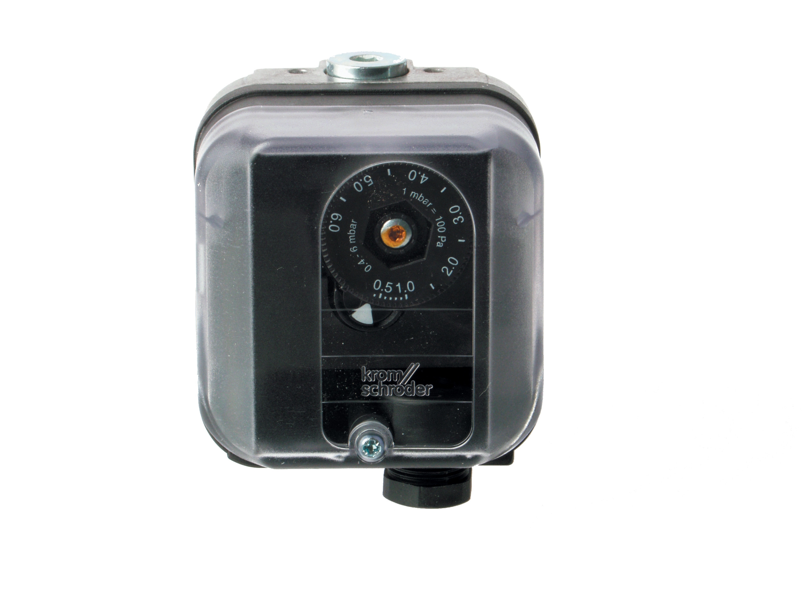
Pressure switches like the Kromschroder DG 50U/6 protect against dangerous pressure conditions. Failures manifest as nuisance shutdowns, failure to shut down during overpressure, or inability to start burners.
Diagnosis Protocol:
1. Isolate the pressure source: First, confirm the pressure reading at the switch location matches your system design. Pressure switches can fail due to incorrect sensing line connection, kinked tubing, or plugged ports. Trace the sensing line from the switch back to the pressure source. Look for crimp fittings that may have separated or tubing routing that creates siphon effects.
2. Manual actuation test: Most pressure switches include mechanical test buttons. With the system safely de-energized, press the test button. You should hear an audible click indicating internal switch actuation. No click means the switch mechanism failed. Multiple clicks or inconsistent operation indicates contact chatter—a sign of imminent failure even if the switch currently functions.
3. Measure actuation pressure: Connect a precision pressure gauge to the sensing port. Slowly increase pressure using a hand pump. Record the exact pressure at which the switch actuates (makes electrical contact). The Kromschroder DG 50U/6 SIL 3 rated switch should actuation within ±3% of rated setpoint. If actuation pressure drifts more than 5% from design specification, replace the switch immediately—contact degradation has begun.
4. Test electrical continuity: Using an ohmmeter, verify that the switch contacts actually open and close at the actuation point. Zero ohms during operation, infinite resistance during non-operation. If continuity remains constant regardless of pressure, internal contact failure has occurred.
Common Root Causes:
- Disconnected or kinked pressure sensing lines
- Debris in pressure ports (water, dirt, crystallized residue)
- Contact degradation from hundreds of switching cycles
- Incorrect setpoint configuration during installation
- Corrosion of external switch housing allowing moisture ingress
Electronic Control and Relay Failures
Modern burner systems rely on sophisticated electronic relay modules like the Brahma Relay CE 191.4 for complex safety logic. When these fail, the entire burner control sequence collapses.
Diagnosis Protocol:
1. Power supply verification: Before assuming relay failure, confirm stable power delivery. Use a multimeter to measure voltage at relay input terminals. Acceptable range typically 220-240V AC for European systems, 110-120V AC for some North American applications. Voltage fluctuations exceeding ±10% indicate electrical supply problems—contact your facility's electrical department. The Brahma Relay CE 191.4 operates at 230V 50/60Hz and requires stable supply for reliable ionization current monitoring.
2. Terminal voltage mapping: Map every terminal voltage during normal operation and during fault conditions. Create a comparison table showing measured values against schematic expectations. This reveals which internal relay stages malfunction. Voltage appears where expected except at one terminal? That identifies the failed stage.
3. Output load testing: Disconnect output terminals from solenoid valves or other loads. Using a multimeter, measure voltage present at output terminals. If voltage exists without load but disappears when reconnected, the relay output stage can't deliver sufficient current—internal contact resistance has increased, indicating imminent failure.
4. Ionization current measurement: Many relay systems like the Brahma CE 191.4 measure ionization current to verify flame presence. The system requires minimum 1.2 µA ionization current. Using specialized ionization current meters (multimeters cannot measure this), verify minimum ionization during combustion. Values below 0.8 µA indicate combustion problems, not relay failure. Values below 0.5 µA universally indicate relay sensor failure.
Common Root Causes:
- Power supply instability causing relay logic errors
- Solder joint cracks on relay circuit boards from thermal cycling
- Capacitor failures (typically after 8-10 years of operation)
- Contact degradation from switching high inductive loads
- Programming errors in logic-based relay systems
Pilot Light and Ignition System Failures
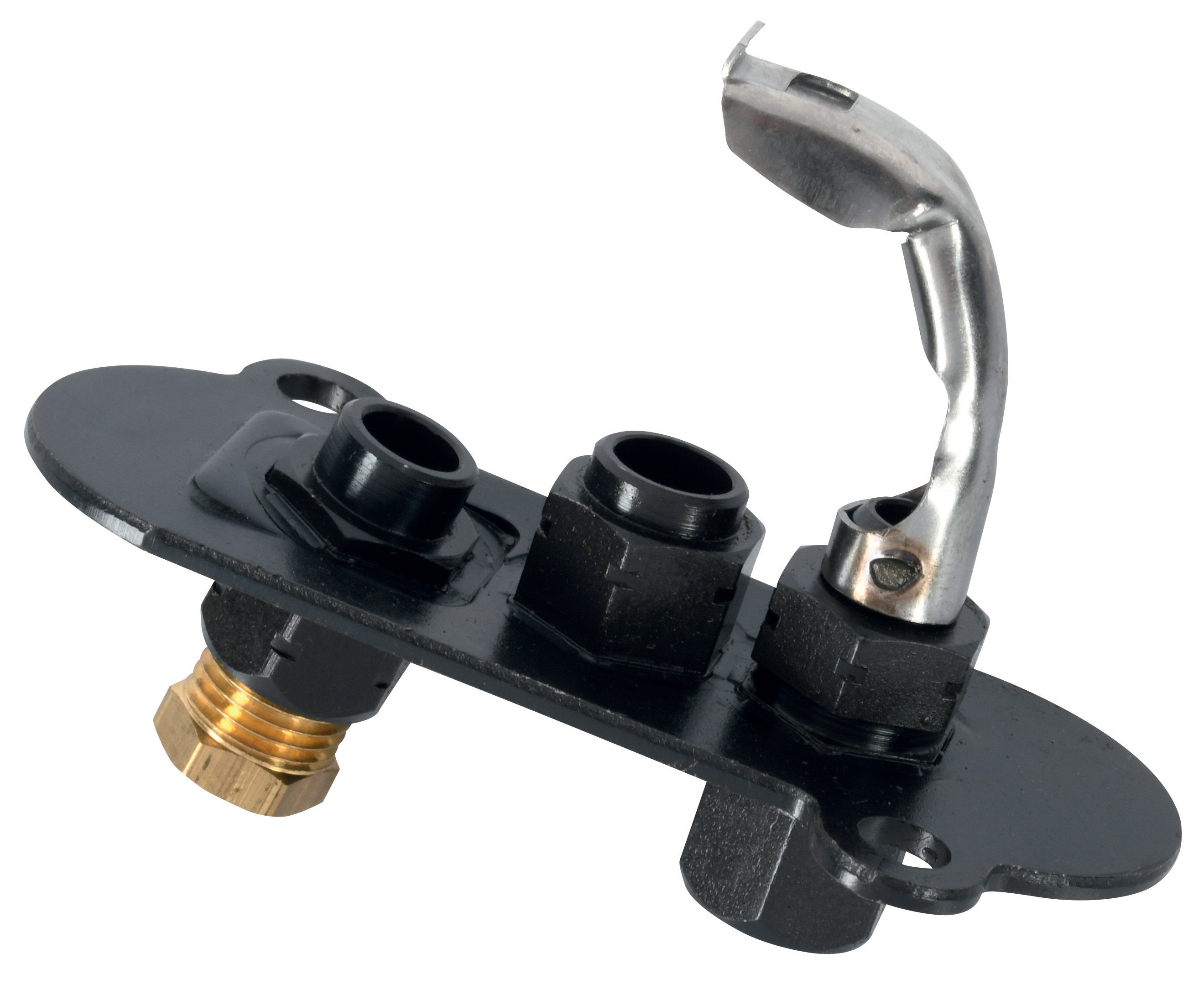
Pilot lights like the Sit universal pilot light often represent the weak link in startup sequences. Failures here prevent main burner ignition entirely.
Diagnosis Protocol:
1. Visual flame observation: Observe the pilot flame color and stability. Proper pilot flames burn steady blue near the base with slight yellow at the tip. Orange or yellow flames throughout indicate incomplete combustion—check fuel quality and air supply. Flickering or unstable pilots suggest wind drafts, poor positioning, or inadequate fuel supply pressure.
2. Fuel supply pressure to pilot: Measure pressure at the pilot fuel inlet using a low-pressure gauge (0-5 PSI range). Gas pilots typically require 3.5-4.5 inches water column. Oil pilots require 0.5-1.0 PSI. Pressure outside these ranges prevents reliable ignition. Check for fuel supply filter blockage—a common cause of inadequate pressure.
3. Ignition electrode inspection: The pilot light ignition electrode must maintain precise spacing (typically 3-4 mm gap) and alignment toward the pilot flame. Visual inspection often reveals obvious damage or corrosion. With fuel valve closed and ignition system powered, you should see a spark between electrodes when viewing in darkness. No spark indicates transformer failure or broken ignition wire.
4. Pilot flame signal at control module: Once the pilot flame establishes, does the flame detection signal reach the main control relay? With pilot operating, measure voltage at the flame signal input of your main control. No voltage indicates flame detector failure; correct voltage at the detector but missing at the control indicates wiring problems.
Common Root Causes:
- Misaligned or damaged ignition electrodes
- Blocked fuel supply to pilot from contaminated filters
- Corroded or fouled pilot burner orifices
- Failed ignition transformer
- Vibration causing pilot flame instability
Section 3: Advanced Diagnostic Tools and Resources
Essential Testing Equipment
Effective diagnostics require appropriate tools. Minimum toolkit for plant maintenance personnel:
- Digital multimeter with millivolt capability: Essential for all electrical measurements. Budget $30-50 for adequate quality.
- Pressure gauges (low pressure 0-5 PSI and high pressure 0-300 PSI): Required for pressure switch and fuel system diagnostics. $40-80 for the set.
- Specialized ionization current meter: Required for flame detection analysis in modern systems. $200-400 investment, but essential for facilities with electronic relays.
- Combustion analyzer: Measures oxygen, CO, and flame temperature. Confirms combustion quality as root cause of detection failures. $500-1500 investment pays dividends through reduced diagnostic time.
- Thermal imaging camera: Identifies temperature abnormalities indicating component stress or failure. Optional for advanced facilities, but increasingly valuable. $300-1000.
These tools transform diagnostic time from hours of trial-and-error into minutes of systematic measurement.
Documentation and Knowledge Management
Successful plant managers create diagnostic reference documents specific to their equipment:
Create System Schematic Diagrams: Obtain original equipment schematics and annotate with actual measured values during normal operation. Label every test point, terminal, and component. When failures occur, technicians follow the schematic and identify deviations within minutes rather than hours.
Maintain Component Replacement History: Log every component failure, including failure mode, replacement date, and operating hours at failure. This reveals patterns—for example, if flame detectors consistently fail after 18 months in your environment, schedule preventive replacement at 15 months rather than waiting for failure.
Develop Equipment-Specific Checklists: Create laminated troubleshooting checklists for each major control system in your facility. Guide technicians through the diagnostic sequence, ensuring consistency and reducing missed steps.
Document Previous Failures: When a complex fault occurs, document the complete diagnostic process and solution. Future similar failures resolve 10 times faster using documented experience rather than starting from zero.
Section 4: Preventive Strategies and Long-Term Reliability
Condition Monitoring Implementation
Instead of waiting for failure, proactive plants monitor control system health continuously:
Establish Normal Performance Baselines: During commissioning, record how the complete control system should behave under every operating condition—startup, steady-state, load changes, and shutdown. This baseline becomes your reference for detecting degradation before failure occurs.
Trend Critical Parameters: Track response times, pressure readings, and sensor signals over weeks and months. Gradual degradation appears in trending data weeks before catastrophic failure. A pressure switch that required 45 PSI to actuate might gradually drift to 50 PSI, then 55 PSI. At 48 PSI, schedule replacement rather than waiting for failure at 60 PSI.
Monitor Component Age: Controls & Safety components have defined operational lifecycles. Flame detectors typically operate reliably for 5-7 years; relay modules for 8-10 years; solenoid valves for 10-15 years depending on fuel quality. Calendar-based replacement prevents age-related failures even if no symptoms appear.
Training and Capability Building
Diagnostic capability requires trained personnel:
- Assign diagnostic responsibility: Designate specific technicians as control system specialists. Provide manufacturer training for your specific equipment. 3G Electric provides technical resources and can connect you with manufacturer training programs.
- Cross-training secondary technicians: Backup capability prevents single-point-of-failure dependence on one person.
- Document decision trees: Convert oral knowledge into written diagnostic sequences accessible to all technicians.
- Regular competency verification: Quarterly review of diagnostic techniques ensures knowledge retention and identifies knowledge gaps requiring additional training.
Strategic Component Inventory
Reliable plants maintain critical spare components:
High-priority spares (maintain 1-2 units): Flame detectors (Siemens QRB4A-B036B40B), pressure switches (Kromschroder DG 50U/6), and main control relays (Brahma Relay CE 191.4). These failures halt production immediately, justifying rapid replacement inventory.
Medium-priority spares (maintain 1 unit): Pilot lights (Sit universal pilot light), electrodes (CBM stainless steel electrode), and solenoid valves. These fail less frequently but cause extended downtime if unavailable.
Long-lead-time monitoring: Track lead times from suppliers for components that typically require 2-4 weeks procurement. When lead times lengthen due to supply chain disruptions, increase safety stock proportionally.
With 35+ years of global distribution experience, 3G Electric maintains extensive inventory of these critical components, typically delivering within 2-3 business days for emergency orders. Establishing relationships with reliable distributors eliminates diagnostic time-to-resolution complications caused by component unavailability.
Conclusion
Controls & Safety system diagnostics transforms from mysterious art into systematic science when plant managers implement structured troubleshooting protocols. By understanding system architecture, establishing performance baselines, and following logical diagnostic sequences, your facility eliminates the guesswork from safety equipment failures.
The investment in proper diagnostic tools, technician training, and documentation infrastructure pays dividends immediately through reduced downtime, and strategically through improved safety culture and regulatory compliance. Plant managers who master these diagnostic approaches report 40-60% reductions in unplanned shutdowns and significantly improved equipment lifecycle management.
3G Electric's 35+ years distributing these critical controls & safety components globally positions us to support your diagnostic and replacement needs. Whether you require specific components like the Kromschroder DG 50U/6 pressure switches or comprehensive system support, we maintain the inventory and expertise to keep your operations running safely and reliably.