Understanding Pressure Switch Failures in Controls & Safety Systems
Pressure switches operate as critical safety devices in burner control circuits, detecting fuel pressure, combustion air pressure, and system faults before they escalate into hazardous conditions. In Singapore's tropical climate and high-demand industrial settings, pressure switches experience accelerated wear due to humidity, temperature fluctuations, and continuous operation cycles.
When a pressure switch malfunctions, the burner control system may fail to ignite, lock out unexpectedly, or worse—allow unsafe fuel flow without proper verification. With over 35 years of experience distributing industrial controls, 3G Electric has observed that roughly 40% of burner lockouts in the region stem from pressure switch calibration drift rather than genuine safety conditions.
The Kromschroder DG 50U/6 pressure switch is rated SIL 3 and meets rigorous EN 1854 safety standards, making it a reliable choice for verifying proper system response. However, even premium switches require systematic diagnostic verification to confirm operational integrity.
Diagnostic Procedures for Pressure Switch Testing
Visual Inspection and Mechanical Assessment
Begin troubleshooting by examining the pressure switch physically:
- Connection integrity: Verify all tubing connections are secure and free from corrosion. Singapore's humid environment accelerates oxidation; inspect copper or stainless steel tubing for green patina or salt deposits.
- Diaphragm condition: If accessible, observe the diaphragm for cracks, punctures, or deformation. A compromised diaphragm prevents accurate pressure sensing and will trigger false lockouts.
- Electrical terminals: Check terminal corrosion, loose wire connections, and insulation degradation. Use a dry cloth to clean terminals; apply dielectric grease to prevent moisture ingress.
- Housing damage: Look for dents, stress cracks, or evidence of impact. Physical trauma can shift calibration or cause internal component misalignment.
Pressure Isolation and Continuity Testing
Safely isolate the pressure switch from the live system before electrical testing:
1. Shut down the burner and allow pressure to vent completely.
2. Disconnect the pressure tubing at the switch inlet; cap the tubing to prevent contamination.
3. Use a digital multimeter set to ohms (Ω) to measure continuity across the switch terminals.
4. For a normally open switch, resistance should be infinite (open circuit) at rest; when pressure is manually applied via a hand pump, resistance should drop to near zero (closed circuit).
5. For a normally closed switch, the relationship reverses—low resistance at rest, infinite at pressure.
6. If resistance fails to change across the switch contacts, internal contacts are either welded or damaged; replacement is required.
Calibration Drift Verification
Pressure switches gradually lose calibration accuracy due to diaphragm fatigue and temperature cycling:
- Obtain the original calibration specification from the burner manufacturer or switch datasheet.
- Connect a calibrated pressure gauge in parallel with the switch using a tee fitting.
- Slowly increase system pressure using a hand pump or regulated air supply.
- Note the pressure reading on the gauge when the switch contacts change state (you will hear or feel an audible click).
- Compare this actuation pressure to the specification. Acceptable drift is typically ±3% of rated pressure.
- If drift exceeds tolerance, recalibration or replacement is necessary.
Safety Interlock Circuit Verification and Electrical Fault Diagnosis
Understanding Interlock Circuit Architecture
Modern burner control systems use redundant interlock circuits to ensure safe shutdown. These circuits typically include:
- Pressure switches (fuel pressure, combustion air, draft pressure)
- Temperature limit switches (high-limit cutouts)
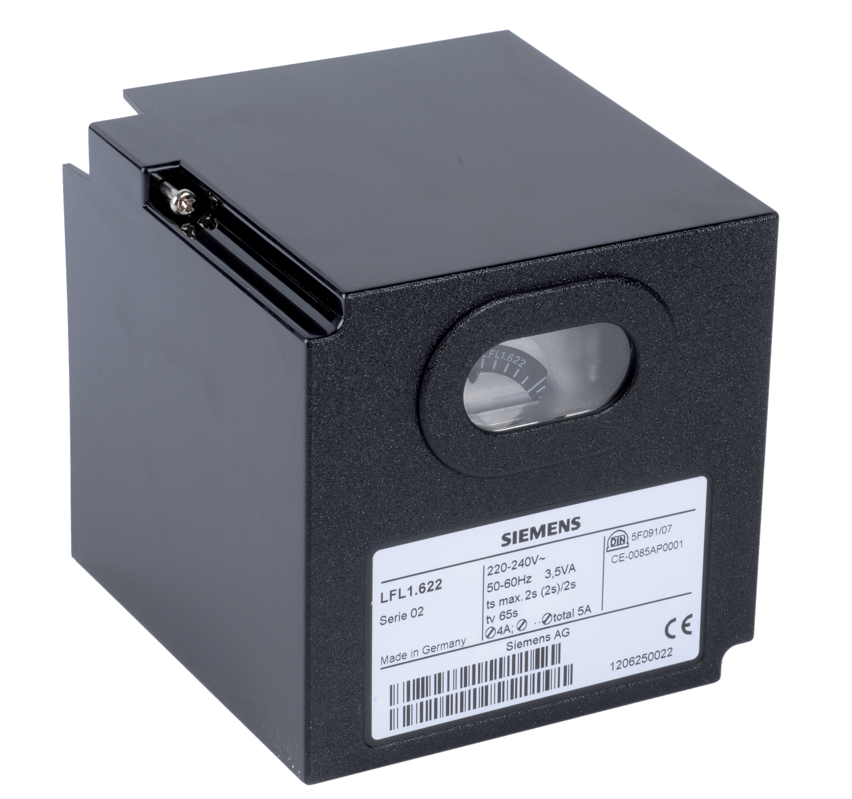
- Flame monitoring relays such as the Siemens LFL 1.622 safety control unit
- Solenoid valve de-energize circuits that cut fuel supply on fault detection
All components must complete a continuous electrical path to allow burner operation. Breaking any link in this path—whether intentionally or due to fault—should immediately de-energize fuel solenoids.
Systematic Interlock Testing Procedure
Step 1: Visual Wiring Inspection
- Trace all interlock wires from pressure switches to relay contacts to solenoid valve coils.
- Inspect insulation for cracks, abrasion, or rodent damage—common in Singapore's warehouse and plant environments.
- Confirm all terminal connections are crimped or soldered, not twisted and taped.
- Check for water intrusion into terminal blocks or connector housings; corrosion will increase electrical resistance and delay circuit response.
- With the burner in safe shutdown mode, manually trigger each pressure switch using a hand pump or by blocking air intake.
- Observe that the burner immediately fails to ignite or shuts down if already running.
- Record the response time; safety-critical systems should respond within 1–2 seconds.
- If the burner continues to operate despite an interlock trigger, the circuit is broken or mis-wired.
- Use a clamp-on ammeter to measure coil current when the interlock circuit is energized.
- A typical solenoid valve coil draws 200–400 mA; low current (<100 mA) indicates a weak or failing coil.
- Check the relay contact resistance using a multimeter; clean contacts should measure <0.5 Ω.
- If relay contacts are pitted or corroded, replace the relay unit. The Kromschroder BCU 570WC1F1U0K1-E relay is a drop-in replacement for many legacy systems and provides direct ignition support.
- For AC circuits, use an insulation tester (megohm meter) set to 500 V to measure resistance between the circuit and ground.
- Resistance should be >5 MΩ (megohms) for a safe circuit.
- If resistance is <1 MΩ, moisture or contamination is present; dry the components or replace them.
- Do not attempt this test while the burner is energized; always ensure all power is isolated.
Pressure Regulation Failures and Their Impact on Safety Interlocks
Pressure regulation and pressure monitoring are interdependent. If a pressure regulator fails, it may trick pressure switches into reporting false safe conditions.
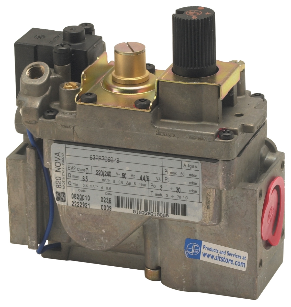
Gas Block Pressure Regulation Issues
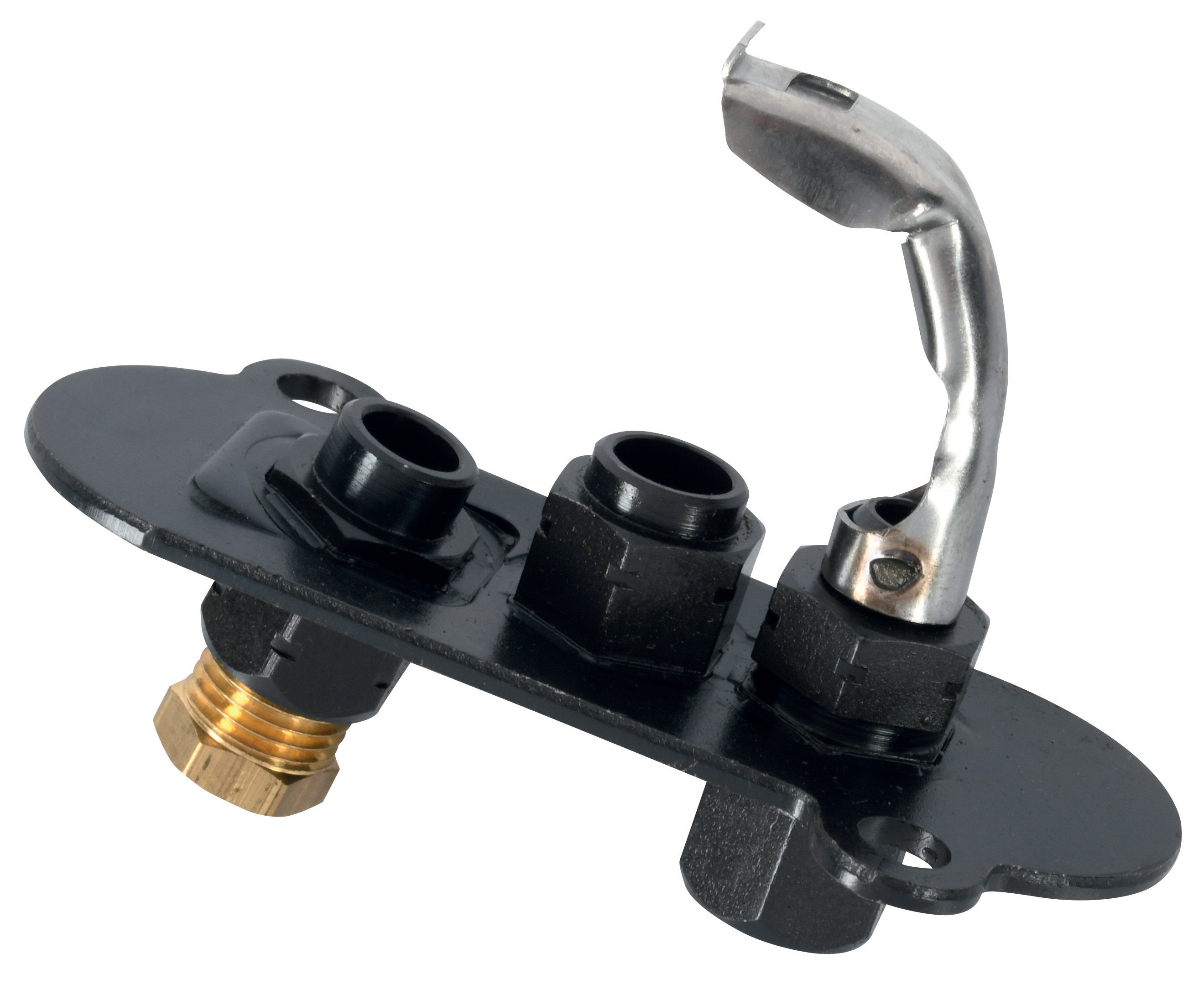
The Sit Minisit gas block 0710218 integrates thermoelectric supervision, pressure regulation, and temperature control in a single compact unit—common in European and Asian burner designs. When gas pressure becomes unstable:
- Symptom 1: Burner ignites but pilot light extinguishes within 5–10 seconds (pressure drops below minimum threshold).
- Symptom 2: Combustion becomes unstable; flame lifts or falls back from nozzle.
- Diagnosis: Measure gas inlet pressure at the gas block using a low-pressure gauge (0–500 mbar scale). Compare to the burner's rated inlet pressure (typically 20–50 mbar for pilot, 200–500 mbar for main stage).
- Remedy: If inlet pressure is within spec but outlet pressure is erratic, the pressure regulator diaphragm may be damaged. Replace the entire gas block or regulator cartridge.
- Prevention: Install a coarse strainer upstream of the gas block to prevent dirt from clogging the regulator's orifice.
Interlock Pressure Switch Sensitivity Issues
A pressure regulator that oscillates (hunting) will cause pressure switches to chatter, repeatedly triggering and releasing interlock circuits:
- Symptom: Burner cycles on and off in rapid succession, or display shows repeated fault codes.
- Diagnosis: Connect a low-pressure transducer with a digital display to the pressure tap point. A stable burner should show <±5% pressure variation.
- Remedy: Adjust the regulator spring tension (if adjustable) to reduce oscillation amplitude. If oscillation persists, replace the regulator.
Commissioning and Preventive Maintenance for Pressure Switch Systems
Initial Setup Checklist
When installing a new burner or replacing pressure switches:
1. Verify pressure switch orientation: Most switches are direction-sensitive; fuel inlet must connect to the "P" port and exhaust to "E" or remain open.
2. Use correct gauge adapters: Ensure pressure tubing is copper or stainless steel (minimum 3 mm OD). Plastic tubing degrades in high-temperature environments.
3. Calibrate before commissioning: Apply known pressure and confirm actuation points are within ±3% of specification.
4. Document all measurements: Maintain a logbook with baseline pressure readings, switch actuation points, and interlock response times. This baseline is invaluable for future troubleshooting.
Quarterly Maintenance Program
- Month 1: Visually inspect all pressure switch connections for corrosion or leaks. Apply dielectric grease to electrical terminals.
- Month 2: Test interlock circuits by manually triggering each pressure switch; confirm burner shuts down within 2 seconds.
- Month 3: Perform a full pressure calibration check if the burner operates >500 hours per month.
- Month 4: Clean or replace inlet strainers and pressure gauge snubbers to maintain accurate readings.
Replacement Triggers
Replace pressure switches if:
- Calibration drift exceeds ±5% after adjustment attempts.
- Electrical continuity testing shows erratic results or contacts are pitted.
- Diaphragm is visibly cracked or leaking.
- Response time to pressure changes exceeds 3 seconds.
- The switch has been in continuous service for >10 years (diaphragm fatigue is inevitable).
The Kromschroder DG 50U/6 remains a top choice for burner control applications in Singapore due to its SIL 3 rating and robust construction suitable for high-humidity environments.
Conclusion
Pressure switches and safety interlocks are non-negotiable elements of burner control systems. Systematic diagnostic procedures—visual inspection, continuity testing, calibration verification, and functional loop testing—enable maintenance teams to confidently verify safety system integrity. In Singapore's tropical climate, accelerated corrosion and humidity make quarterly maintenance schedules essential. By following the procedures outlined in this guide and leveraging industry-standard components from 3G Electric's extensive catalog, your maintenance team can prevent unsafe burner operation and extend equipment service life. When in doubt, consult the original equipment manufacturer's documentation or contact 3G Electric's technical support team for region-specific guidance.