Understanding Controls & Safety System Architecture for Maintenance
Controls and safety systems in industrial burner applications form the critical backbone of reliable, compliant operations. For maintenance teams managing these systems, understanding the relationship between control components and safety devices is essential before attempting diagnostics or repairs.
A typical controls and safety system consists of pilot light assemblies that continuously monitor flame presence, solenoid valves that regulate gas flow based on control signals, relay bases that process electrical switching, and supervisor components that verify safe operating conditions. These elements work interdependently—a failure in one component can cascade through the entire system, creating dangerous conditions or complete shutdown.
With over 35 years of experience as a global industrial equipment distributor, 3G Electric has supported maintenance teams across diverse industries in managing these complex systems. The key to effective maintenance lies in understanding both individual component function and system-level interactions. This practical approach prevents costly downtime while maintaining the safety standards your facility demands.
Systematic Diagnostics: Testing Controls & Safety Components in the Field
When controls and safety systems malfunction, maintenance teams must follow systematic diagnostic procedures to isolate problems quickly and safely. Random component replacement wastes time and resources; structured testing identifies root causes.
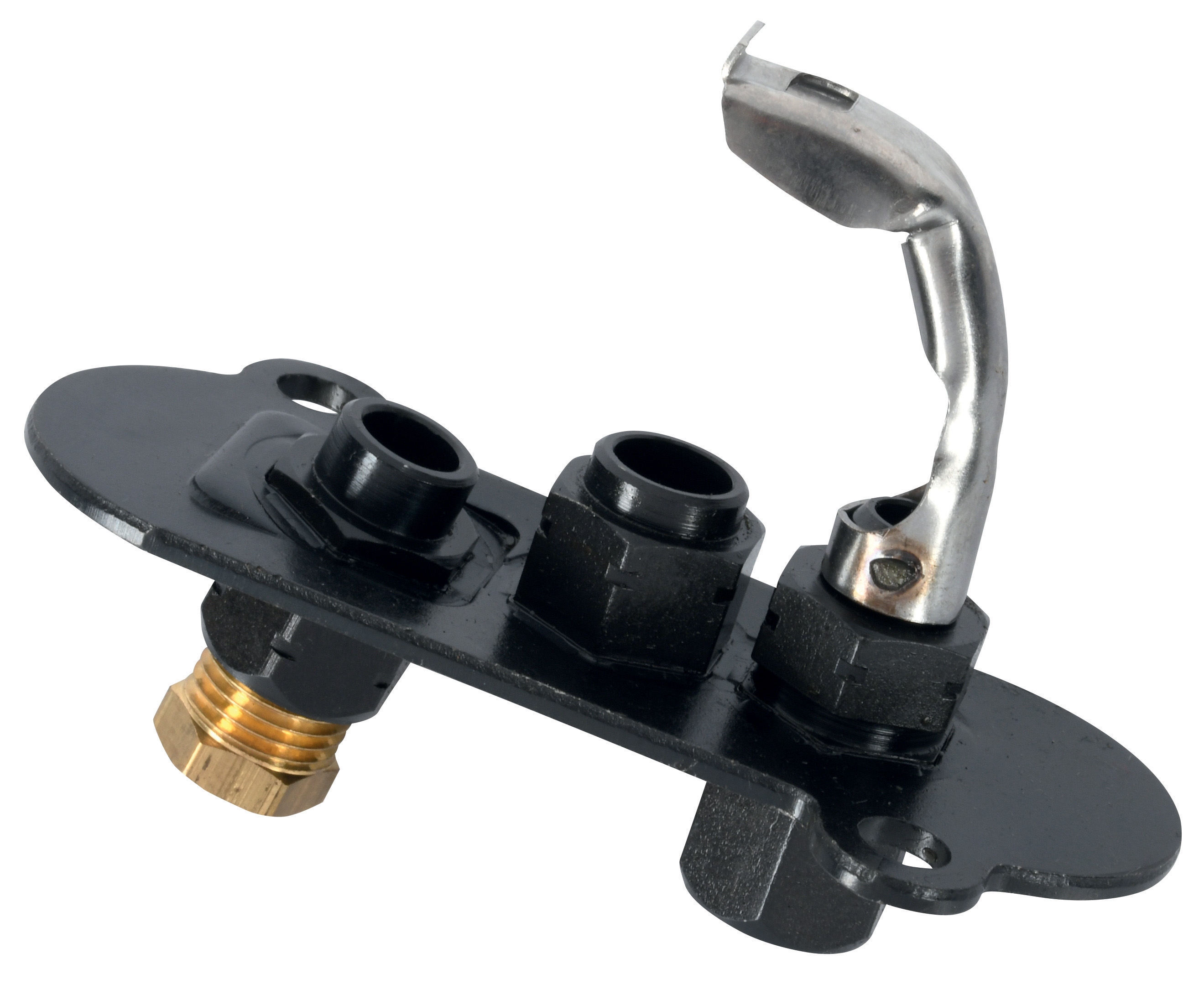
Pilot Light and Flame Detection Testing
The pilot light serves as your system's primary safety supervisor. Begin diagnostics by visually inspecting the pilot flame itself. A healthy pilot should burn steadily without flicker or discoloration. Pilot lights like the CBM 1-flame pilot light 0.150.082 and CBM Pilot light 1 flame 0140026 require clear gas supply and proper electrode positioning.
Test pilot light continuity using your multimeter:
- Disconnect the pilot light electrical connection at the thermoelectric element
- Set your multimeter to resistance (ohms) mode
- Test continuity across the thermoelectric terminals
- A reading between 10-50 ohms indicates a functional element; infinite resistance signals a failed unit requiring replacement
If the pilot ignites but produces no electrical signal, the thermoelectric element itself has failed. If the pilot won't ignite at all, check gas supply at the pilot burner connection using a pressure gauge (typical specifications: 0.5-1.0 kPa).
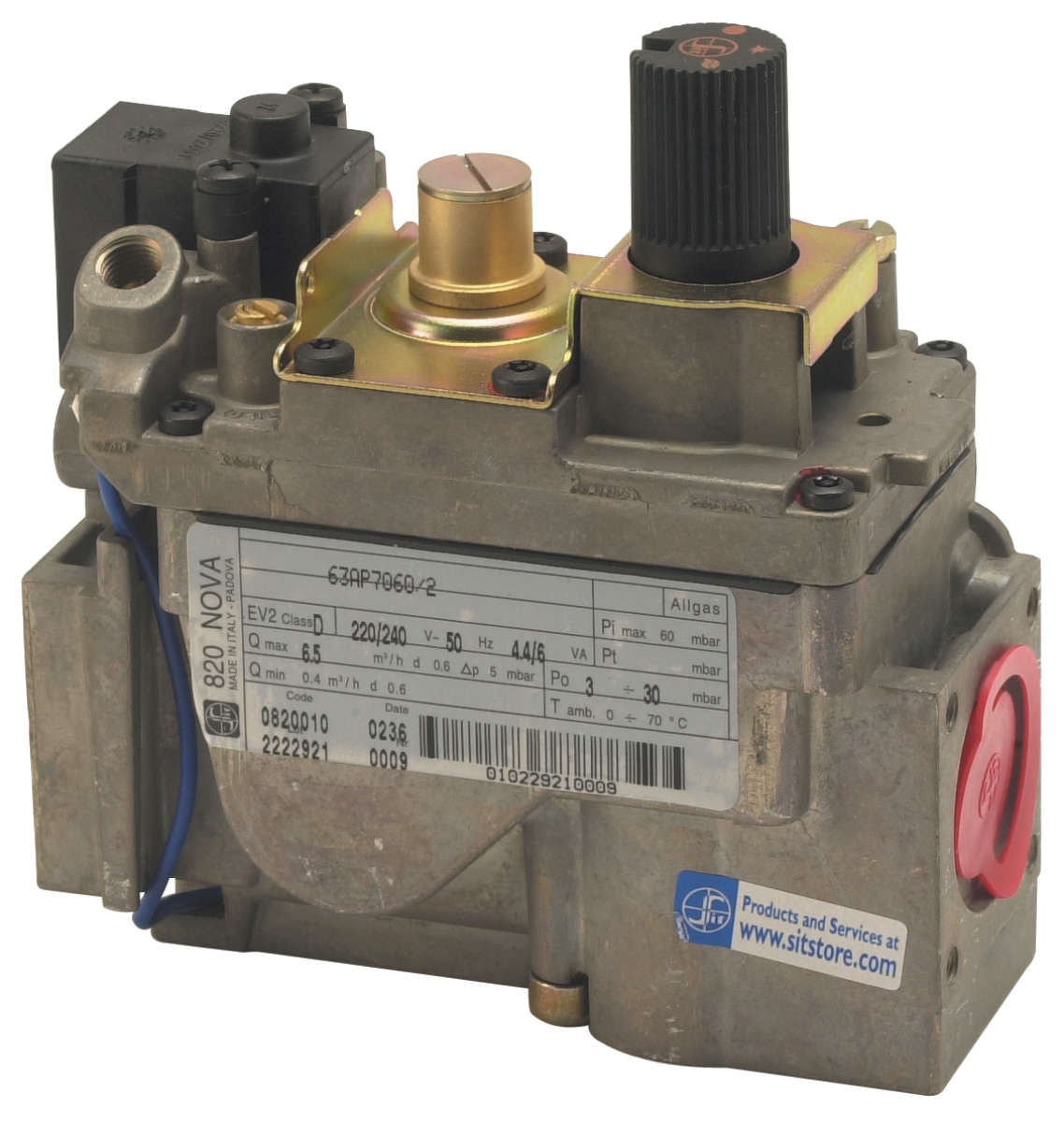
Solenoid Valve Function Verification
Solenoid valves like the CBM VCS 1E25R/25R05NNWL3/PPPP/PPPP double solenoid valve control main gas flow based on control signals. Testing involves both electrical and mechanical verification.
Electrical testing:
- Measure voltage at the solenoid coil terminals with power on
- Standard operating voltage is typically 24V AC or DC (verify your specific model)
- If voltage is present but the valve doesn't energize, the solenoid coil is failed
- If no voltage reaches the solenoid, trace back through the control circuit to identify the interruption
Mechanical testing (after depressurizing the gas line):
- Manually depress the solenoid plunger—it should move freely without grinding sounds
- When released, it should snap back smoothly
- Rough movement or grinding indicates internal wear requiring valve replacement
- Listen for the distinctive "click" when 24V is applied; absence of this sound suggests coil failure
Relays like the CBM Relay CM391.2 30.5 1.2 mounted on bases such as the CBM Base LGK AGM17 process control signals throughout your system. Test these components by:
- Verifying input signal voltage at relay terminals (typically 24V logic)
- Applying test voltage directly to the relay coil while listening/feeling for the mechanical click
- Measuring continuity across relay contacts before and after energization
- Contacts should show infinite resistance when de-energized and near-zero when energized
Relay failure often manifests as stuck contacts (welded closed or frozen open). These cannot be repaired and require replacement with verified compatible units.
Preventive Maintenance: Reducing Controls & Safety Emergencies
Proactive maintenance prevents emergency shutdowns and extends component service life. Implement these procedures quarterly or per your equipment manufacturer's specifications.
Pilot Light Inspection and Cleaning
Dust and carbon accumulation block gas supply and reduce thermoelectric element efficiency. Quarterly maintenance includes:
- Shut off gas supply and allow the system to cool completely
- Visually inspect the pilot burner for carbon buildup or blockage
- Using a fine wire or specialized pilot cleaner tool, gently clear any obstructions from the burner orifice
- Verify the electrode spacing (typically 1-2mm) using a feeler gauge
- Reinstall and test for steady ignition and good thermoelectric output (minimum 15mV DC)
Solenoid valves experience wear from pressure cycling and electromagnetic stress. Implement these checks:
- Listen during normal operation for any grinding, chattering, or unusual sounds
- Document valve response time—sluggish opening or closing indicates internal wear
- Inspect downstream gas lines for leaks, which suggest internal valve leakage
- Check for moisture in the gas supply; water contamination accelerates solenoid failure
- If your facility experiences frequent humidity or moisture issues, install a gas dryer upstream of the solenoid
Relays accumulate carbon deposits and contact corrosion over time. Maintenance includes:
- Measure contact resistance using your multimeter (should be <1 ohm when closed)
- If resistance exceeds 5 ohms, contacts are degraded and the relay should be scheduled for replacement
- Test the relay for chatter—rapid on/off cycling that indicates mechanical wear
- Document relay switching frequency; high-cycle applications require more frequent inspection
Common Controls & Safety Failures: Recognition and Response
Maintenance teams must recognize failure patterns to respond appropriately and prevent safety incidents.
System Won't Ignite or Stays in Lockout
This typically indicates pilot light failure, solenoid valve obstruction, or control signal interruption. Diagnostic sequence:
1. Verify manual gas supply valve is fully open
2. Test pilot light ignition and thermoelectric output
3. Measure voltage at the main solenoid valve
4. If voltage is present but the valve won't open, test the valve mechanically
5. Check for gas supply pressure—insufficient pressure prevents proper valve operation
Intermittent Flame Loss
This dangerous condition typically indicates marginal pilot light output or thermoelectric element degradation. The pilot ignites initially but produces insufficient electrical signal for reliable flame supervision.
Diagnostic response:
- Measure thermoelectric output voltage continuously during operation
- Output should remain stable above the minimum threshold (typically 18-20mV DC)
- Fluctuating voltage indicates an aging thermoelectric element requiring replacement
- Check for draft or vibration near the pilot—movement reduces flame stability
Gas leaking from a solenoid valve despite being de-energized indicates internal seat wear. This requires immediate action:
- Shut down the system immediately
- Test the valve with gas supply pressure isolated
- If leakage persists, the valve must be replaced; internal repair is not viable
- Install the replacement valve carefully, verifying inlet/outlet connections match specifications
Relay failures or control circuit interruptions prevent proper system operation. Testing approach:
- Verify 24V power supply at the control panel is stable
- Test each relay by applying voltage directly to its coil terminals
- Use an ohmmeter to verify all control circuit continuity
- Check for loose connections at terminal blocks or connectors
- If a relay fails testing, replace it with an exact specification match
Safety Considerations During Controls & Safety Maintenance
Maintenance work on controls and safety systems carries inherent risks. Always observe these critical safety practices:
Before Any Maintenance:
- Shut down the burner and confirm the pilot light is extinguished
- Close the main gas supply valve and verify pressure gauges read zero
- Lock and tag the main power supply disconnect
- Allow the system to cool completely before handling any components
- Never assume a solenoid valve is de-energized—verify with a multimeter
- Never apply voltage to components with gas lines pressurized unless explicitly testing under controlled conditions
- Wear appropriate PPE including safety glasses
- Use properly calibrated test equipment (multimeter, pressure gauge)
- Never force mechanical components—excessive force indicates misalignment or damage
- If you detect a gas leak, evacuate the area and call emergency services before investigating further
- Verify all connections are tight before pressurizing the system
- Test the system through multiple on/off cycles before returning to normal operation
- Document all component testing results and any replacements performed
- Schedule follow-up inspection if you've replaced any safety-critical components
Building a Controls & Safety Maintenance Program
Rather than responding only to failures, successful maintenance teams develop proactive programs. This approach, refined through 35+ years of industry experience at 3G Electric, reduces emergency downtime and extends component life.
Documentation and Tracking
Maintain detailed records of:
- Component installation dates and manufacturers
- Testing results and measurements (thermoelectric voltage, relay resistance, gas pressure)
- Any adjustments or component replacements
- Failure patterns or recurring issues
This data reveals trends—for example, pilot lights consistently failing after 18 months may indicate a gas quality issue, not just component defects.
Inventory Management
Stock critical replacement components based on failure history:
- Pilot light assemblies (both types in your fleet)
- Solenoid valve coils and complete valve assemblies
- Relay modules matching your control system specifications
With spare components on hand, maintenance teams respond to failures in hours rather than days, minimizing production impact.
Training and Knowledge Sharing
Ensure your maintenance team understands the complete control system, not just component replacement. Include:
- Annual refresher training on diagnostic procedures
- Review of safety protocols specific to your facility
- Documentation of system-specific quirks or known issues
- Cross-training so multiple technicians can handle critical maintenance
Conclusion: Controls & Safety as a Maintenance Priority
Controls and safety systems deserve prioritized maintenance attention because they directly protect both equipment and personnel. The procedures outlined in this guide—systematic diagnostics, preventive maintenance cycles, and proper safety practices—represent the practical foundation of reliable industrial operations.
With complex, interconnected components from suppliers like CBM represented through 3G Electric's distribution network, maintenance teams need both technical knowledge and quality replacement parts readily available. By implementing systematic troubleshooting, preventive inspection schedules, and thorough documentation, your facility maintains the safety standards and operational reliability that modern industrial operations demand.
For specific component specifications, compatibility questions, or technical support, consult your equipment documentation or contact 3G Electric—our 35+ years supporting global industrial operations means we understand the unique demands of your maintenance program.