Understanding Controls & Safety in Flame Monitoring Systems
Flame monitoring represents the backbone of modern Controls & Safety architectures in industrial burner systems. Unlike older mechanical flame detection methods, contemporary burner controls rely on ionization or ultraviolet (UV) sensing technology to continuously verify flame presence during operation. When flame monitoring sensors fail, safety interlocks activate immediately, triggering non-resettable lockouts that shut down production until the fault is cleared.
For procurement engineers, understanding how these sensors operate and fail is essential for inventory management, preventive maintenance planning, and cost control. Over 35 years distributing industrial equipment globally, 3G Electric has observed that flame monitoring failures account for approximately 40% of unplanned burner shutdowns in manufacturing environments. The good news: most failures are preventable through proper sensor selection, installation verification, and maintenance protocols.
Common Flame Monitoring Sensor Failures and Diagnostic Procedures
Ionization Sensor Degradation
Ionization flame detection works by measuring ion current across a sensing electrode in the flame zone. This electrode becomes fouled by combustion byproducts, insulation moisture, and carbon deposits over time. When ion current drops below the sensitivity threshold, the burner control interprets this as flame loss and locks out.
Diagnostic indicators:
- Intermittent lockouts during normal operation (flame visually present)
- Lockout occurs after 15-30 seconds of successful ignition
- System resets successfully after brief cooling period
- Multimeter reading at sensor terminals shows <1 microampere ion current
- Sensor electrode spacing widened by thermal cycling
- Carbon buildup on electrode surfaces from incomplete combustion
- Moisture contamination in sensor lead insulation
- Loose sensor installation allowing vibration-induced movement
- Incorrect sensor positioning relative to flame envelope
The Brahma Relay CM 31 F TW10/TS5 incorporates ionization flame monitoring with adjustable sensitivity thresholds, allowing technicians to compensate for minor electrode fouling before complete sensor replacement becomes necessary. Procurement teams should stock these relays with sensitivity documentation for field tuning during maintenance windows.
UV Sensor Optical Degradation
Ultraviolet flame detection uses a photoresistor that changes resistance when exposed to UV radiation emitted by the flame. Unlike ionization sensors, UV sensors fail through optical path obstruction rather than electrical fouling.
Diagnostic indicators:
- Lockout occurs immediately after ignition attempt (no flame recognition)
- UV sensor lens appears cloudy, yellowed, or dark under visual inspection
- Sensor resistance reads >1 megohm when flame is actively burning
- No response to manual lens cleaning
- Intermittent recognition of flame with excessive sooting
- Thermal lens discoloration from sustained high-temperature exposure
- Quartz window fouling from combustion products and equipment vibration
- Incorrect sensor mounting angle blocking flame radiation path
- Sensor specification mismatch for fuel type (some UV sensors optimized for oil, others for gas)
- Inadequate housing ventilation causing thermal creep beyond sensor rating
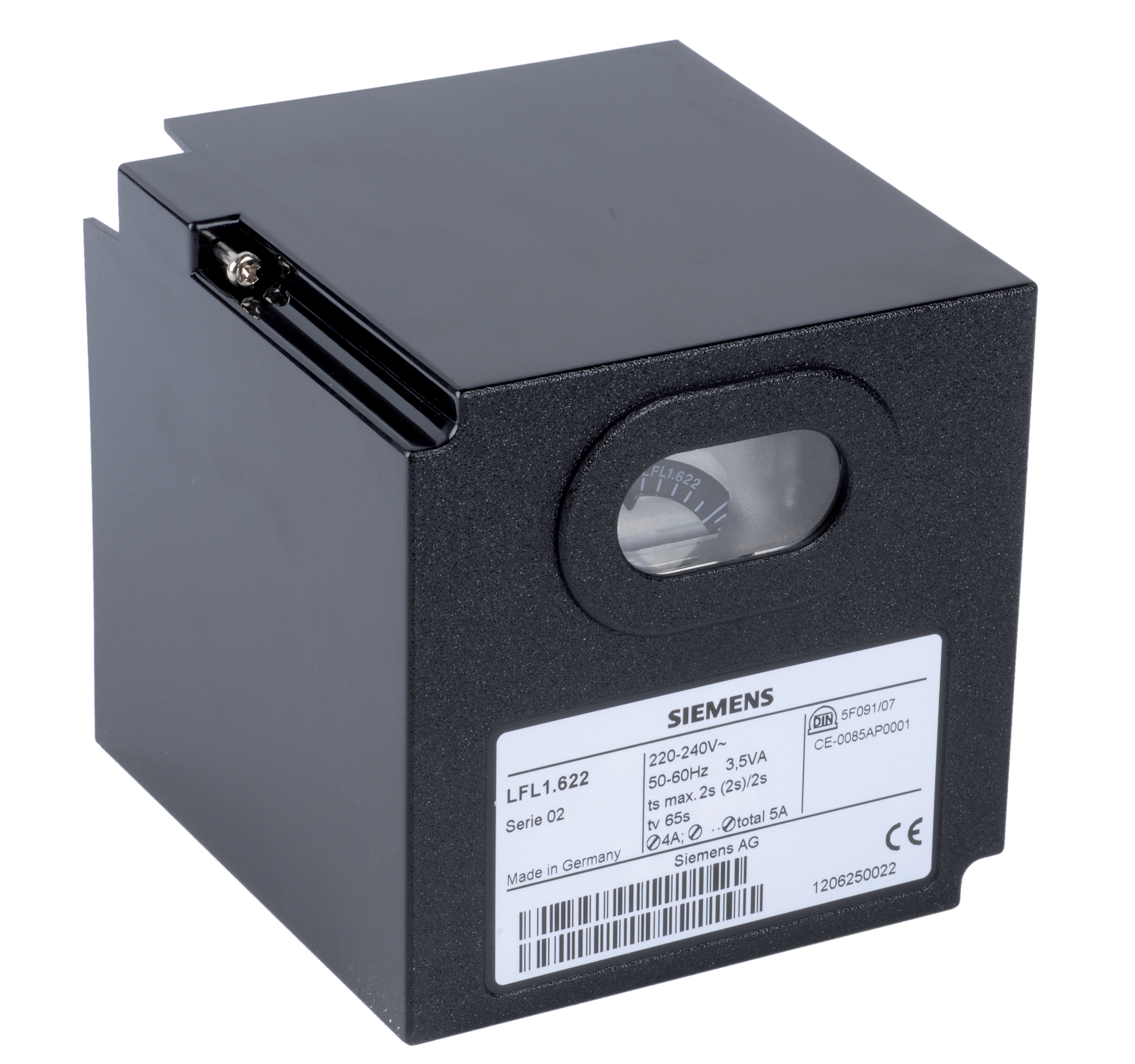
The Siemens Relay LFL 1.622 provides UV/ionization hybrid detection, allowing automatic sensor switching if one technology fails. For procurement engineers managing multi-fuel burner fleets, this redundancy significantly reduces emergency repair costs and production interruptions.
Sensor Cable and Electrical Connection Failures
Flame sensor circuits operate at extremely low signal levels (microamperes for ionization, nanoamperes for UV). Even minor electrical faults in leads, connectors, or relay terminals can cause complete signal loss.
Diagnostic indicators:
- Consistent lockout pattern regardless of flame quality or burner adjustment
- Multimeter shows no continuity or high resistance (>10k ohms) in sensor circuit
- Visual inspection reveals corroded connector pins or loose terminal connections
- Lockout clears when sensor lead is mechanically flexed or connector is reseated
- Sporadic failures correlating with temperature cycles or equipment vibration
- Corrosion on terminal contacts from moisture or salt-air environments
- Improper sensor cable gauge selection causing voltage drop over distance
- Connector type incompatibility between relay and sensor manufacturer
- Mechanical strain on sensor leads from inadequate conduit support
- Insulation deterioration from thermal cycling or UV exposure
When specifying sensor replacement parts, procurement engineers must verify connector type compatibility. The Kromschroder and Brahma relay models used across global operations often use different connector standards, making cross-supplier substitution problematic without proper adaptation hardware.
Controls & Safety Pressure and Interlock Verification
Flame monitoring sensors operate within a broader Controls & Safety system that includes pressure switches, solenoid valve interlocks, and control relays. Even if the flame sensor functions perfectly, upstream safety failures can trigger false lockouts that appear to originate from sensor faults.
Pressure Switch Integration
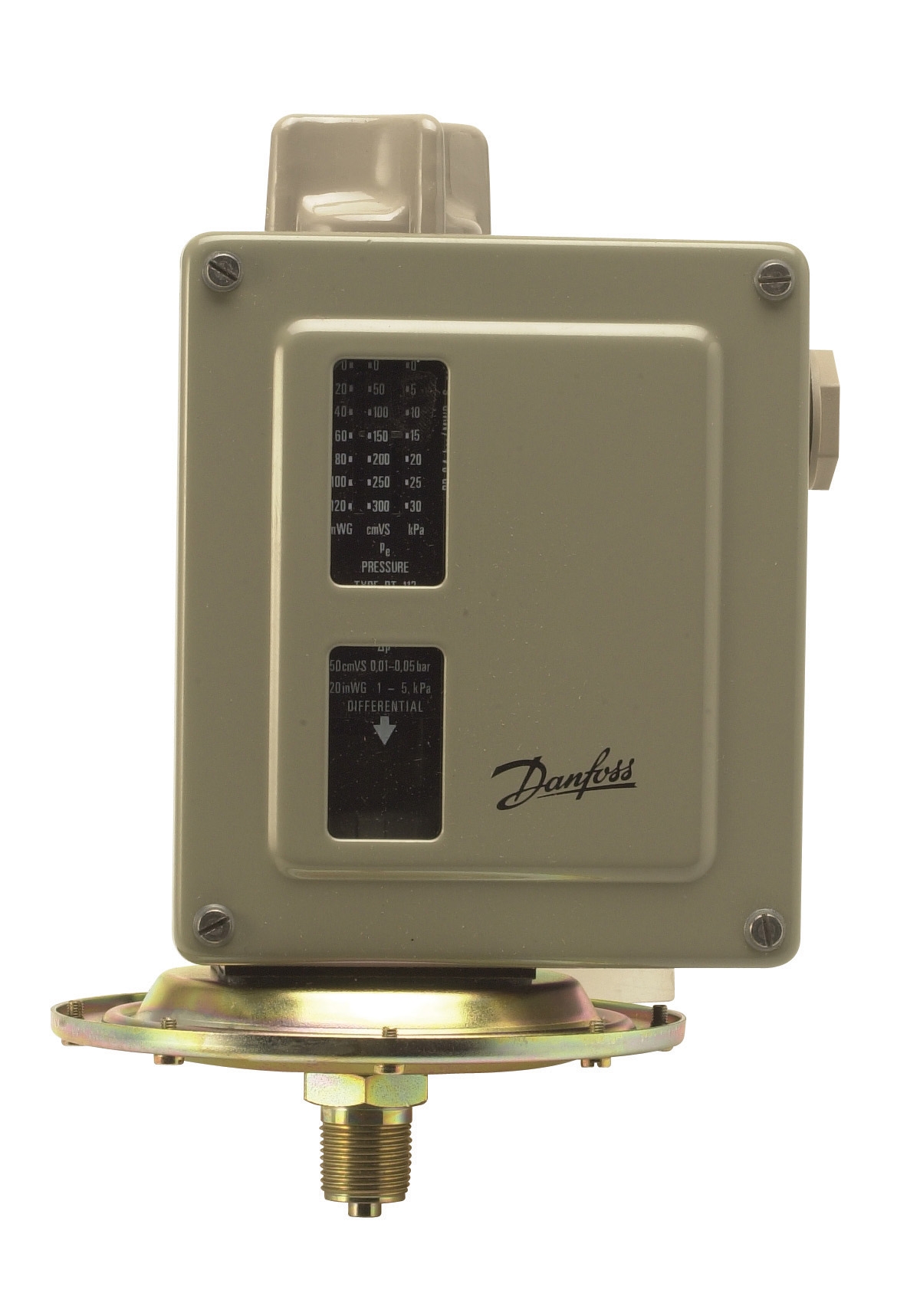
The Kromschroder Pressure switch DG 50U/6 monitors fuel supply pressure and sends signal to the control relay confirming proper delivery conditions. If this pressure switch fails—either stuck in open position or with sluggish response—the control relay receives conflicting signals and defaults to safety lockout.
Verification procedure:
1. Record pressure gauge reading at burner fuel inlet
2. Simultaneously measure electrical signal at pressure switch terminals using multimeter
3. Manually open/close pressure switch manually while monitoring relay response
4. Confirm pressure switch electrical hysteresis matches equipment specification (typically 0.3-0.5 bar differential)
Pressure switch failures represent 20% of apparent sensor faults in our experience. Before authorizing sensor replacement, always verify pressure switch functionality through direct electrical testing.
Gas Control Block Safety Validation
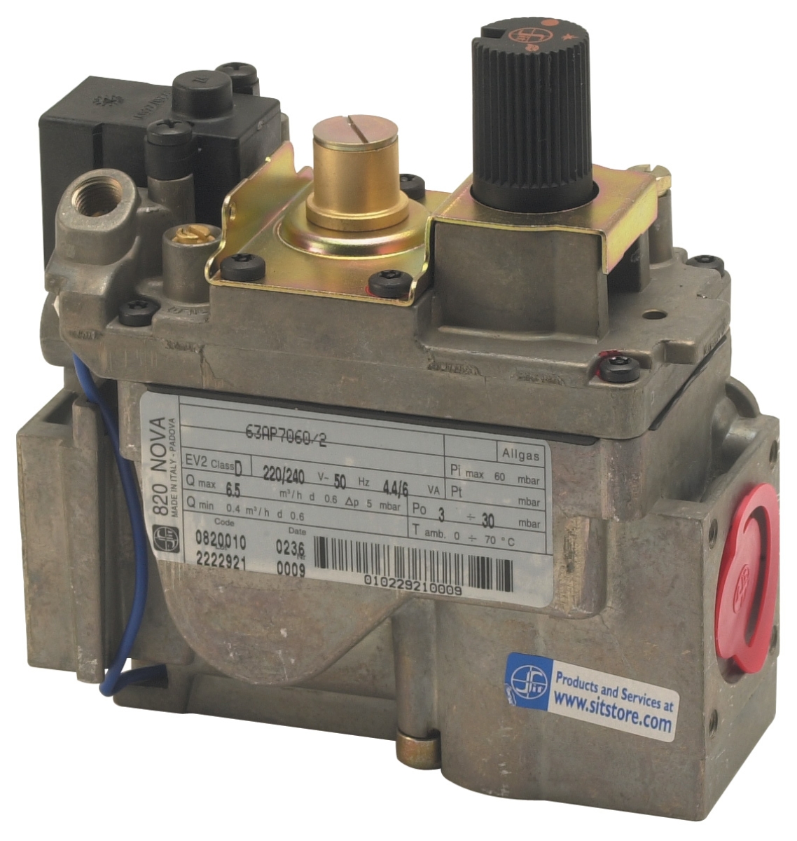
The Sit Minisit gas block 0710218 integrates pressure regulation, temperature control, and solenoid safety shutoff in a single compact unit. When this block develops internal leakage or valve stiction, the burner cannot maintain safe operating conditions, and safety interlocks shut down the system.
Safety validation steps:
1. Isolate gas supply and bleed pressure downstream of the gas block
2. Apply regulated pressure above the inlet and monitor for internal leakage (pressure should hold for 5 minutes minimum)
3. Energize solenoid valve and measure gas flow at outlet (should increase linearly with pressure increase)
4. De-energize solenoid and verify complete shutoff within 2 seconds
5. Test thermostat function by applying heat source and monitoring pilot gas cutoff temperature
Gas block failures often cause intermittent lockouts misattributed to flame sensors because the system cycles unpredictably as internal valve response becomes sluggish. Procurement teams should include gas block pressure/leakage test equipment in maintenance budgets.
Sensor Selection and Specification for Global Operations
Fuel Type Compatibility
Flame sensors perform differently across natural gas, propane, biogas, and fuel oil burners. UV sensors designed for oil burner applications (with heavy soot production and lower flame UV intensity) may not provide sufficient sensitivity for clean-burning natural gas flames. Conversely, gas-rated ionization sensors may over-respond to electrical noise in industrial environments with variable fuel quality.
When procuring replacement sensors, specifications must include:
- Fuel type(s): Natural gas, propane, LPG, fuel oil, or dual-fuel capability
- Flame intensity range: Expected UV radiance or ion current for target burner size
- Environmental class: Temperature extremes, humidity, electrical noise immunity
- Certification standard: EN 746-2 for industrial burners (compliance verified by Kromschroder Relay BCU 570WC1F1U0K1-E)
Redundancy and Safety Integrity Levels (SIL)
Critical applications require redundant flame monitoring with voting logic (2oo3 configuration—two of three sensors must confirm flame). The Kromschroder BCU 570WC1F1U0K1-E supports both direct ignition and intermittent pilot modes with EN 676 compliance, enabling flexible deployment across burner types.
For SIL 3 applications (as specified in Kromschroder Pressure switch DG 50U/6 certification), procurement engineers must ensure:
- Sensor replacement components carry matching SIL certification
- Installation procedures documented for regulatory compliance
- Maintenance intervals established with sensor manufacturer specifications
- Spare parts inventory maintained for critical systems (minimum 2x annual consumption)
Maintenance and Preventive Strategies
Scheduled Sensor Inspection Protocol
Establish quarterly visual inspections for all flame sensors:
1. Optical check: UV sensor lenses should be clear, colorless, and free of deposits
2. Mechanical verification: Sensor mounting hardware tight; no visible gaps between sensor tip and flame envelope
3. Electrical continuity: Measure resistance at sensor terminals (ionization typically 10-100 ohms cold; UV 500k-2 megohm cold)
4. Connector condition: Inspect for corrosion, moisture, or loose pins
5. Documentation: Log any resistance drift or visual changes
When resistance trends exceed 20% variance from baseline, schedule sensor replacement during next planned maintenance window rather than waiting for failure.
Environmental Control
Flame sensor reliability depends heavily on installation environment:
- Temperature: Install sensors outside direct flame zone; ambient temperature >80°C degrades electrode life
- Humidity: Enclose sensor cables in conduit with breathable vent caps to prevent moisture trapping
- Vibration: Use rigid conduit support within 300mm of sensor to minimize mechanical stress
- Electrical noise: Route sensor cables separately from power wiring; avoid bundling with VFD or solenoid leads
Procurement and Cost Optimization
With 35 years experience distributing industrial burner controls, 3G Electric has developed supplier relationships ensuring availability of flame monitoring components for legacy and current-generation burner systems. Consider these procurement strategies:
1. Standardization: Consolidate flame sensor specifications across your burner fleet where possible. Using Brahma relays globally reduces training requirements and simplifies spare parts inventory.
2. Bulk purchasing: Flame sensors experience predictable failure cycles. Forecast annual consumption based on fleet size and environmental severity, then purchase 18-month supply at volume discounts.
3. OEM vs. aftermarket: Original manufacturer sensors typically cost 30-40% more but provide warranty coverage. Aftermarket sensors from reputable distributors like 3G Electric offer equivalent performance at lower cost for non-critical applications.
4. Diagnostic equipment: Invest in multimeters and pressure gauges capable of measuring microampere circuits and sub-1-bar pressure differentials. Proper diagnostics prevent unnecessary sensor replacement.
Troubleshooting Decision Tree
Symptom: Immediate lockout after ignition attempt
→ Check pressure switch signal and gas block solenoid energization
→ If pressure/solenoid confirmed, measure sensor resistance
→ If resistance >10x normal baseline, replace sensor
Symptom: Intermittent lockout during stable operation
→ Verify sensor cable continuity and connector seating
→ Clean UV sensor optical surfaces with lint-free cloth
→ Test pressure switch response through full operating range
→ If intermittency persists, replace sensor and gas block simultaneously
Symptom: Lockout requires extended cooling period to reset
→ Measure ambient temperature at sensor location
→ Verify sensor mounting position relative to flame envelope
→ Confirm sensor thermal rating matches installation environment
→ If temperature exceeds sensor rating, relocate sensor or install thermal shielding
Symptom: Lockout clears only after disconnecting and reconnecting sensor
→ Measure resistance at connector terminals and relay terminals separately
→ If resistance normal at sensor but high at relay, clean connector pins
→ If resistance high at sensor, test with multimeter in high-impedance mode (optical surfaces may be fouled)
→ Replace sensor if resistance remains abnormal after cleaning