Understanding Controls & Safety in Flame Detection Systems
Controls & Safety systems protect industrial operations by continuously monitoring flame presence during burner operation. When a flame detection failure occurs, the control system must immediately shut down fuel supply to prevent unsafe conditions—explosions, unburned gas accumulation, and equipment damage.
In Southeast Asian industrial environments, flame detection failures represent approximately 40-50% of all unplanned burner shutdowns. High humidity, dust-laden air, thermal stress from rapid cycling, and sensor contamination create unique challenges for facilities across Singapore, Malaysia, Thailand, and Indonesia. After 35 years as a distributor serving this region, 3G Electric has identified the most common failure patterns and practical resolution strategies that maintenance teams can implement without specialized lab equipment.
Understanding the three components of a flame detection chain—the sensor itself, the control relay that interprets the signal, and the solenoid valve that responds to the relay output—is essential for rapid troubleshooting.
Section 1: Diagnosing Ionization Flame Detection Problems
How Ionization Sensors Work
Ionization sensors detect flame by measuring electrical conductivity in the flame envelope. When gas burns, ions form in the flame, creating a weak DC current (typically 1-5 microamps) that the control relay measures. If this current drops below the relay's sensitivity threshold, the relay interprets the signal as flame loss and triggers a shutdown.
In Southeast Asia's tropical environments, ionization sensors fail more frequently than UV sensors due to:
- High humidity causing electrode corrosion: Moisture combines with combustion byproducts to form conductive films that short-circuit the sensor signal
- Dust and fuel residue buildup: Salt air near coastal facilities and industrial dust accelerate electrode fouling
- Thermal cycling stress: Rapid on-off burner cycles expand electrode materials unevenly, causing fractures in the electrode assembly
Step-by-Step Ionization Sensor Troubleshooting
Step 1: Verify the Problem Location
Before removing equipment, confirm the failure is in the sensor, not the control relay or fuel supply line:
1. Document the exact moment the shutdown occurs (during ignition, after 30 seconds, during steady-state operation)
2. Record ambient temperature and humidity if the facility has monitoring equipment
3. Photograph the burner flame color (orange/yellow indicates proper combustion; blue indicates too-lean mixture)
4. Note whether the same burner fails repeatedly or if failures are random across multiple burners
Step 2: Clean the Ionization Electrode
Most apparent ionization failures resolve after cleaning:
1. Shut down the burner and allow it to cool for 15 minutes minimum
2. Locate the ionization electrode (typically a ceramic-coated rod or probe in the burner head)
3. Use a soft brass brush or fine emery cloth to gently scrub the electrode surface—do NOT use steel wool or abrasive cleaners that damage the ceramic coating
4. Wipe clean with a lint-free cloth dampened with acetone or degreaser
5. Allow acetone to evaporate completely (minimum 5 minutes)
6. Reinstall and test the burner through at least three on-off cycles
Step 3: Test Electrode-to-Ground Resistance
With the burner shut down and cooled, measure resistance between the electrode tip and the burner mounting point using a digital multimeter:
- Expected reading: Infinite resistance (open circuit) when the burner is off and no flame is present
- Problem reading: <1 MΩ (megohm) indicates electrode damage or conductive contamination
- Action: Replace the ionization electrode or burner electrode assembly
Poor fuel quality creates unstable ionization signals:
1. Check the fuel supply pressure with a manometer (should match the burner specification, typically 20-25 mbar for natural gas)
2. Listen for sputtering or irregular combustion sounds
3. If pressure fluctuates >±2 mbar, the regulator needs service or replacement
4. If flame color is inconsistent (yellow-orange instead of blue-yellow), water or sulfur compounds in the gas may be interfering with ionization
Step 5: Verify the Control Relay's Ionization Sensitivity
The control relay must be set to an appropriate sensitivity level for your specific electrode and fuel type. The Brahma Relay CM 31 F TW10/TS5 used in many Southeast Asian facilities allows sensitivity adjustment through an internal potentiometer:
1. With the burner running stably and the flame visible, measure the ionization current using a sensitive ammeter (typically 0.1-5 mA range)
2. Document this value
3. Shut down and allow cooling
4. Access the relay's sensitivity adjustment (consult the relay manual for the specific procedure)
5. Increase sensitivity slightly (one-quarter turn maximum) and retest
6. If shutdown stops occurring, the relay was set too sensitive for the existing electrode condition—document the new setting
7. If shutdown persists even after adjustment, the electrode or relay requires replacement
Section 2: Addressing UV Flame Detection Failures
Why UV Sensors Fail in Southeast Asia
Ultraviolet (UV) sensors detect the UV radiation naturally emitted by flames. Unlike ionization sensors, UV sensors have no electrodes in the flame path, making them immune to electrode corrosion. However, UV sensors fail through different mechanisms in tropical environments:
- Window fouling: The UV-transmitting window becomes opaque due to dust, combustion residue, or insect activity
- Electronic circuit degradation: High humidity penetrates the sensor housing and corrodes internal circuit boards
- Phototube aging: UV photomultiplier tubes gradually lose sensitivity over 5-7 years, particularly in facilities operating 24/7 or in high-dust environments
UV Sensor Cleaning and Restoration
Critical Warning: UV sensors contain quartz windows and delicate optical components. Improper cleaning can permanently damage the sensor.
1. Power down the sensor and allow 10 minutes for internal charge dissipation
2. Locate the UV window (a small quartz lens on the sensor body facing the flame)
3. Use only compressed air (dry, filtered, maximum 2 bar pressure) to gently remove dust from the window surface—never touch with fingers or cloths
4. If a sticky residue is visible, dampen a lens tissue with optical cleaning solution and wipe gently in one direction only
5. Allow the window to air-dry completely before powering on
6. Run the burner and observe if the shutdown pattern changes
If cleaning does not restore normal operation:
1. The phototube may have reached end-of-life—UV sensors typically require replacement every 5-8 years in continuous-duty applications
2. Internal circuit board corrosion may have occurred—replacement is the only remedy
3. Contact your equipment supplier (such as 3G Electric) for OEM replacement sensors compatible with your control relay model
Testing UV Sensor Response
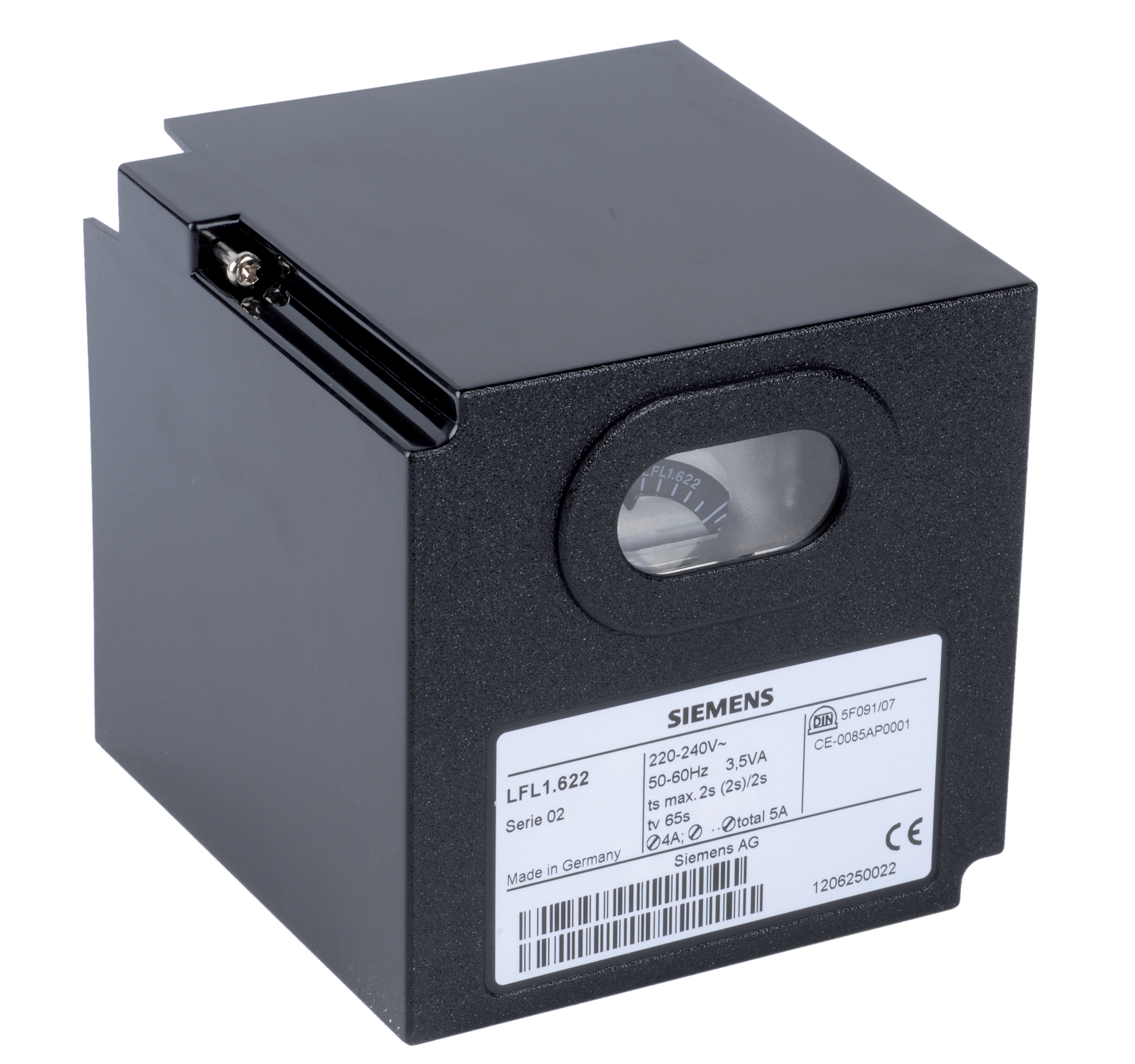
For the Siemens Relay LFL 1.622 and similar UV-enabled control relays:
1. Bring the burner to steady-state operation with a visible, stable flame
2. Temporarily block the UV sensor view of the flame (use a non-flammable baffle) for 3-5 seconds
3. The relay should trigger shutdown within 3 seconds of flame loss detection
4. Remove the baffle; the burner should remain off (the relay will not re-ignite automatically)
5. Reset the relay (typically via a pushbutton on the relay housing) and verify normal ignition sequence resumes
If the relay does not shut down when the flame is blocked, the UV signal chain has failed.
Section 3: Validating Pressure Switches in the Control & Safety Chain
Role of Pressure Switches in Flame Monitoring
Pressure switches provide essential interlocking signals that prevent unsafe burner operation. A pressure switch confirms that fuel is actually reaching the burner before ignition is attempted, and it can force a shutdown if pressure drops during operation (indicating a fuel line rupture or regulator failure).
The Kromschroder Pressure Switch DG 50U/6 is rated for SIL 3 and Performance Level e, meeting the highest safety standards required across Southeast Asian industrial codes. However, pressure switch failures often masquerade as flame detection problems because they interrupt the control signal before the flame is ever ignited.
Pressure Switch Testing Procedure
Test 1: Setpoint Verification
1. Locate the pressure switch on the fuel line (typically 10-20 cm downstream of the main gas valve)
2. Record the setpoint pressure marked on the switch body (typical range: 15-30 mbar for gas burners)
3. Connect a digital manometer to the pressure test point upstream of the pressure switch
4. Slowly increase fuel pressure using the main gas supply valve
5. Note the pressure at which the switch contact closes (activates)—this is the "make" pressure
6. Continue increasing pressure to observe any hysteresis (the switch may deactivate at a slightly higher pressure)
7. Compare measured pressures to the switch nameplate specification
8. If setpoint has drifted >±2 mbar, the switch requires factory recalibration or replacement
Test 2: Electrical Continuity Check
1. Power down all related equipment
2. Use a digital multimeter set to resistance/continuity mode
3. Disconnect the switch electrical connector
4. Measure resistance across the switch terminals
5. With no pressure applied, the switch should show open circuit (infinite resistance)
6. Apply hand-pump pressure to the switch port (if hand-pump port exists) or increase system pressure above the setpoint
7. The switch should show continuity (<1 ohm) when pressurized above setpoint
8. If the switch does not show this behavior, internal contacts are worn or jammed—replacement is required
Test 3: Response Time Measurement
For burners requiring rapid pressure response (typical in Singapore and other developed Southeast Asian markets with strict safety codes):
1. Install a fast-response pressure gauge (0-100 mbar range, ±0.5 mbar accuracy) at the test point
2. Set up a data logger or manual observation to note the exact moment pressure begins rising
3. Have a second person observe the control relay output (typically a LED indicator lights when pressure switch activates)
4. Increase fuel pressure slowly and record the time from when pressure passes the setpoint to when the relay responds
5. Acceptable response time is <500 milliseconds for most industrial burners
6. If response time exceeds 1 second, the switch contacts may be stuck or corroded—replacement is recommended
Pressure Switch Maintenance in Tropical Environments
Southeast Asian coastal facilities experience salt-air corrosion that degrades pressure switch contacts. Standard preventive maintenance:
1. Inspect switch ports quarterly for corrosion (white or blue-green deposits)
2. If corrosion is visible, apply a thin coat of dielectric grease to external metal surfaces
3. For switches exposed to salt spray, consider installing protective covers over the pressure sensing ports
4. Replace the switch every 5 years or after any major fuel system service that might introduce contaminants
Section 4: Integrating Multiple Safety Sensors into Your Troubleshooting Strategy
The Complete Control & Safety Signal Chain
Industrial burners typically employ redundant safety sensors to meet Performance Level d or e standards. Understanding how these sensors work together helps technicians pinpoint exactly where a failure has occurred:
1. Pressure switch confirms fuel availability (prevents ignition if fuel pressure is insufficient)
2. Flame detection sensor (ionization or UV) confirms flame presence within 3 seconds of ignition
3. Air proving switch (on forced-air burners) confirms adequate air velocity before fuel is introduced
4. Temperature sensor (on some systems) prevents re-ignition if the burner head temperature exceeds safe limits
When a burner fails to start or shuts down unexpectedly, testing these sensors in sequence dramatically speeds diagnosis.
Systematic Testing Protocol
For Repeated Shutdowns During Steady-State Operation:
1. First suspect: Flame detection sensor (ionization fouling or UV window blockage)
2. Second suspect: Pressure switch setpoint drift or electrical contact failure
3. Third suspect: Fuel supply instability (regulator calibration loss)
4. Fourth suspect: Control relay sensitivity setting requiring adjustment
For Failure to Ignite:
1. First suspect: Pressure switch not activating (fuel pressure too low or switch setpoint drifted high)
2. Second suspect: Air proving switch failure (if forced-air burner)
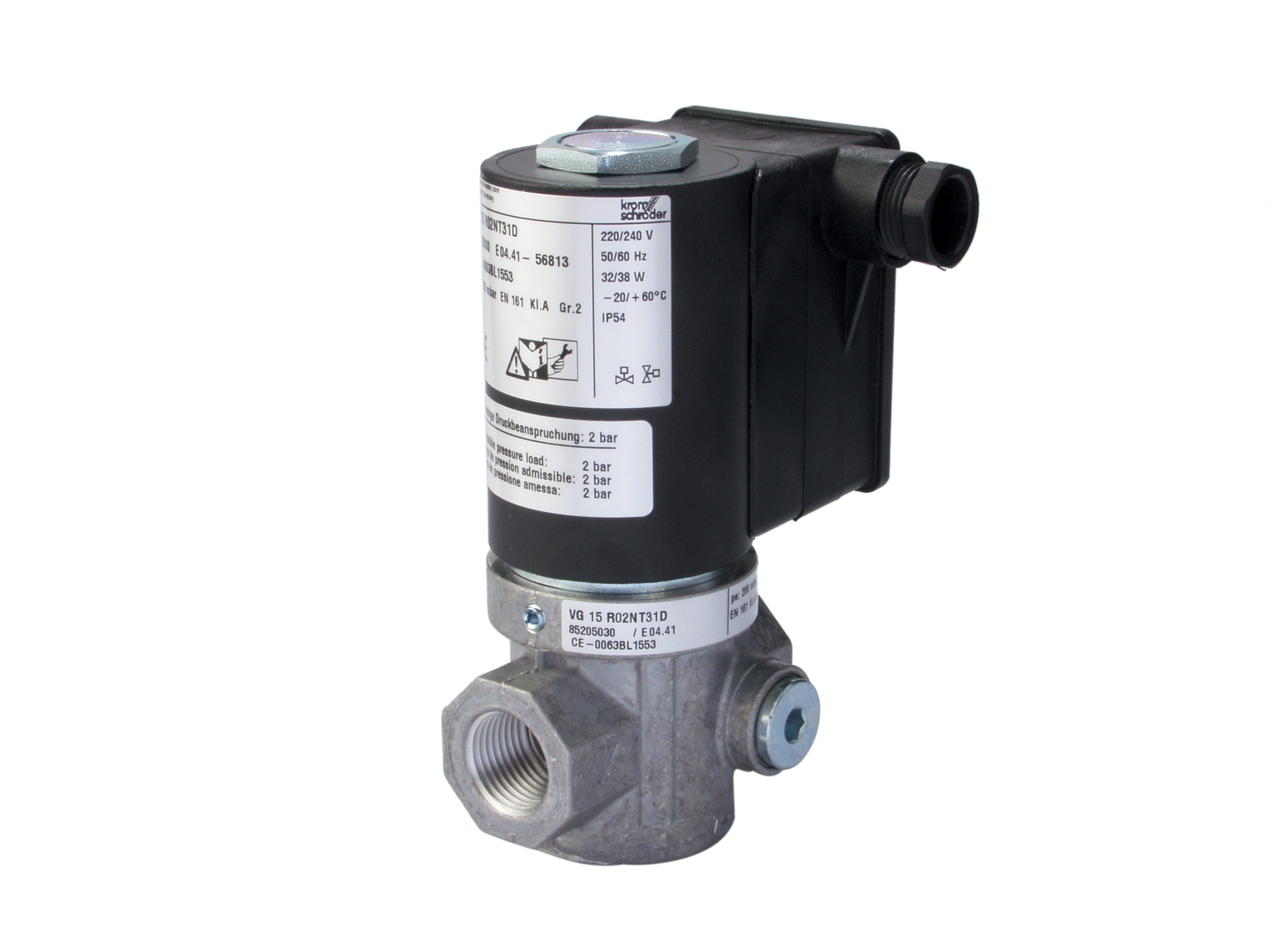
3. Third suspect: Solenoid valve failure (does not open despite relay command)
4. Fourth suspect: Control relay malfunction (not sending ignition signal)
For Intermittent Failures That Are Difficult to Reproduce:
1. Suspect humidity-dependent issues: Clean ionization electrodes, inspect UV window for water droplets
2. Suspect temperature-dependent issues: Check control relay operation at minimum and maximum facility temperatures
3. Suspect pressure fluctuation: Install a digital pressure gauge and log pressure over 24 hours to identify drifts
4. Suspect electrical intermittency: Inspect all control relay connectors for corrosion; apply dielectric grease to connector pins
Using Advanced Diagnostic Tools
While basic multimeters and manometers suffice for most troubleshooting, advanced tools accelerate diagnosis:
- Portable combustion analyzer: Measures CO, CO₂, and O₂ in flue gas; can reveal fuel mixture problems causing flame instability
- Digital manometer with data logging: Records pressure fluctuations over hours; identifies intermittent fuel supply problems
- Clamp-on ammeter with milliamp range: Measures actual ionization current without breaking the electrode circuit
- Thermal imaging camera: Identifies burner head temperature variations that may correlate with shutdown events
3G Electric supplies many compatible diagnostic sensors and control components used across Southeast Asia. Consult with our technical team if your facility requires specialized sensors for your specific burner model and application.
Documentation and Preventive Maintenance
Maintain a troubleshooting log for each burner:
- Date and time of shutdown event
- Ambient temperature and humidity (if available)
- Fuel pressure reading at time of shutdown
- Type of shutdown (flame detection loss, pressure switch failure, or other)
- Corrective action taken
- Result of corrective action
Over time, this log reveals patterns—for example, ionization failures occurring primarily during high humidity monsoon seasons, or pressure switch drift accelerating over calendar time. Patterns enable predictive maintenance: replace ionization electrodes before the monsoon season arrives, or schedule pressure switch calibration every 24 months instead of waiting for failure.
Facilities that implement this data-driven approach reduce unplanned shutdowns by 60-70% and improve burner availability from typical 85% to 95% or higher across the Southeast Asian region.