Controls & Safety: Diagnostic Testing and Performance Validation for Burner Systems
With over 35 years of experience distributing industrial equipment across Asia-Pacific, 3G Electric understands that Controls & Safety systems require rigorous validation testing. Whether you're maintaining HVAC burner systems, industrial boilers, or combustion equipment, diagnostic testing separates reliable operations from unexpected failures. This guide provides industrial professionals with practical, actionable testing procedures that compare different control architectures and help you identify performance issues before they impact facility operations.
Section 1: Understanding Control System Testing Requirements and Equipment Selection
Burner control systems integrate multiple components—relays, solenoid valves, flame detectors, and pressure switches—that must function together within precise tolerances. Diagnostic testing validates that each component meets manufacturer specifications and interacts correctly with system logic.
Why Testing Matters in Singapore's Industrial Environment
Singapore's humid tropical climate, combined with intensive industrial operations, creates challenging conditions for burner controls. Moisture ingress, thermal cycling, and electrical stress accelerate component degradation. Regular diagnostic testing catches degradation before catastrophic failure occurs.
Key testing objectives include:
- Functional verification: Confirm each component operates within rated parameters
- Response time measurement: Validate solenoid valve and relay activation speeds
- Electrical continuity: Detect corroded connections and degraded insulation
- Flame detection reliability: Ensure flame sensors respond appropriately to pilot and main flame
- Safety logic validation: Verify interlocks and permissive functions work as designed
Industrial professionals need three categories of diagnostic tools:
1. Electrical testing: Digital multimeters (minimum 1000V DC/AC rating), insulation testers (500V-1000V range), and clamp meters for current measurement
2. Pressure testing: Analog and digital pressure gauges (0-1 bar and 0-10 bar ranges) with ±2% accuracy for gas line validation
3. Response time measurement: Oscilloscopes (for advanced diagnostics) or dedicated control system analyzers that measure relay closure and solenoid valve opening times
The Satronic Relay DMG 970-N MOD.01 and Siemens LME 22 233C2 relay require different test procedures because they interface with different flame detection technologies. Your test protocol must align with each component's architecture.
Section 2: Comparative Testing Procedures for Burner Control Relays
Control relays form the logic center of burner systems. Testing procedures differ significantly based on relay type and flame detection method used.
Testing the Satronic DMG 970-N MOD.01 Relay
The Satronic Relay DMG 970-N MOD.01 operates at 50Hz or 60Hz with 220/240V or 110/120V supply, and works with IRD 1020 and UVD 971 flame detectors. Testing this relay involves:
1. Supply voltage verification: Measure actual supply voltage at relay terminals. Compare against rated voltage (220/240V or 110/120V depending on configuration). Voltage should remain within ±10% during operation. If voltage drops exceed this range, investigate transformer capacity or wiring resistance.
2. Flame signal injection: Connect a known good flame detector signal source to the relay's input terminals. Measure response time from signal arrival to relay output activation. The DMG 970-N should energize within 2-3 seconds for IRD detection and 1-2 seconds for UVD detection. Compare against baseline measurements to identify degradation trends.
3. Safety shutdown timing: Interrupt the flame signal and measure de-energization time. The relay should cut gas supply within 4 seconds maximum (per EN 298 standard). Slower shutdowns indicate potential logic degradation.
4. Insulation resistance: Using a 500V insulation tester, measure resistance between each terminal pair and ground. Values should exceed 100 MΩ. Lower values indicate moisture ingress requiring component replacement.
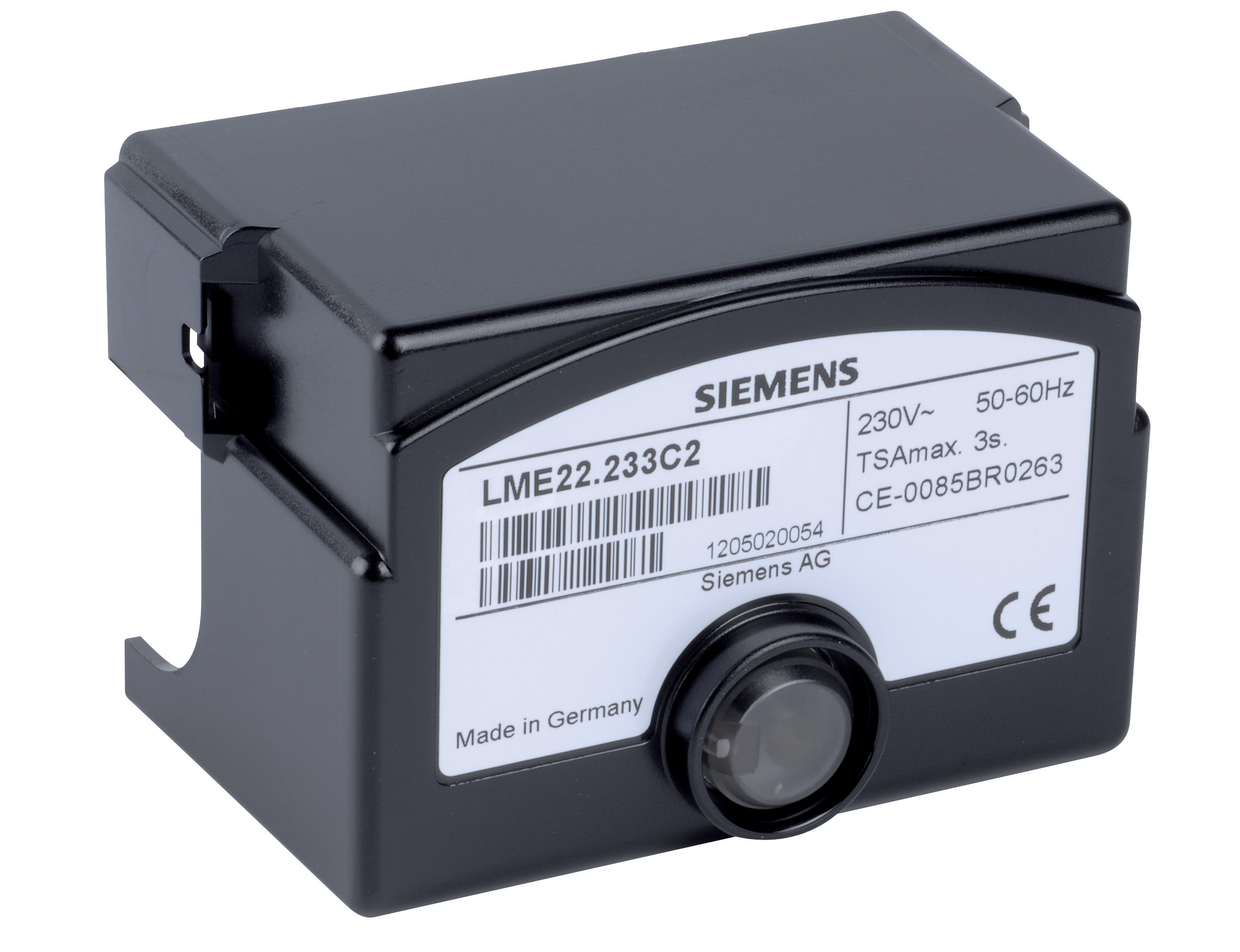
Testing the Siemens LME 22 233C2 Relay
The Siemens LME 22 233C2 supports both ionization and QRA flame detection at 120V~ or 230V~ (50/60 Hz). Testing differs because this relay processes different flame signal characteristics:
1. Dual-mode flame detection testing: If your system uses AGQ3 device compatibility, test both ionization and QRA inputs separately. Measure DC voltage on the ionization electrode (typically 50-150V). For QRA inputs, measure AC signal amplitude. Document baseline values for trend analysis.
2. Lockout function validation: Many facilities operate dual-burner systems. Verify the Siemens relay correctly prioritizes lockout sequences when multiple flame signals are present. Test by simulating flame loss on one burner while maintaining flame on the second.
3. Bleed period measurement: The LME 22 includes a bleed period after ignition where low flame signals don't trigger shutdown. Measure this period using an oscilloscope or control analyzer. Typical duration is 4-8 seconds. Compare against specification to identify logic drift.
Comparative Testing Advantage
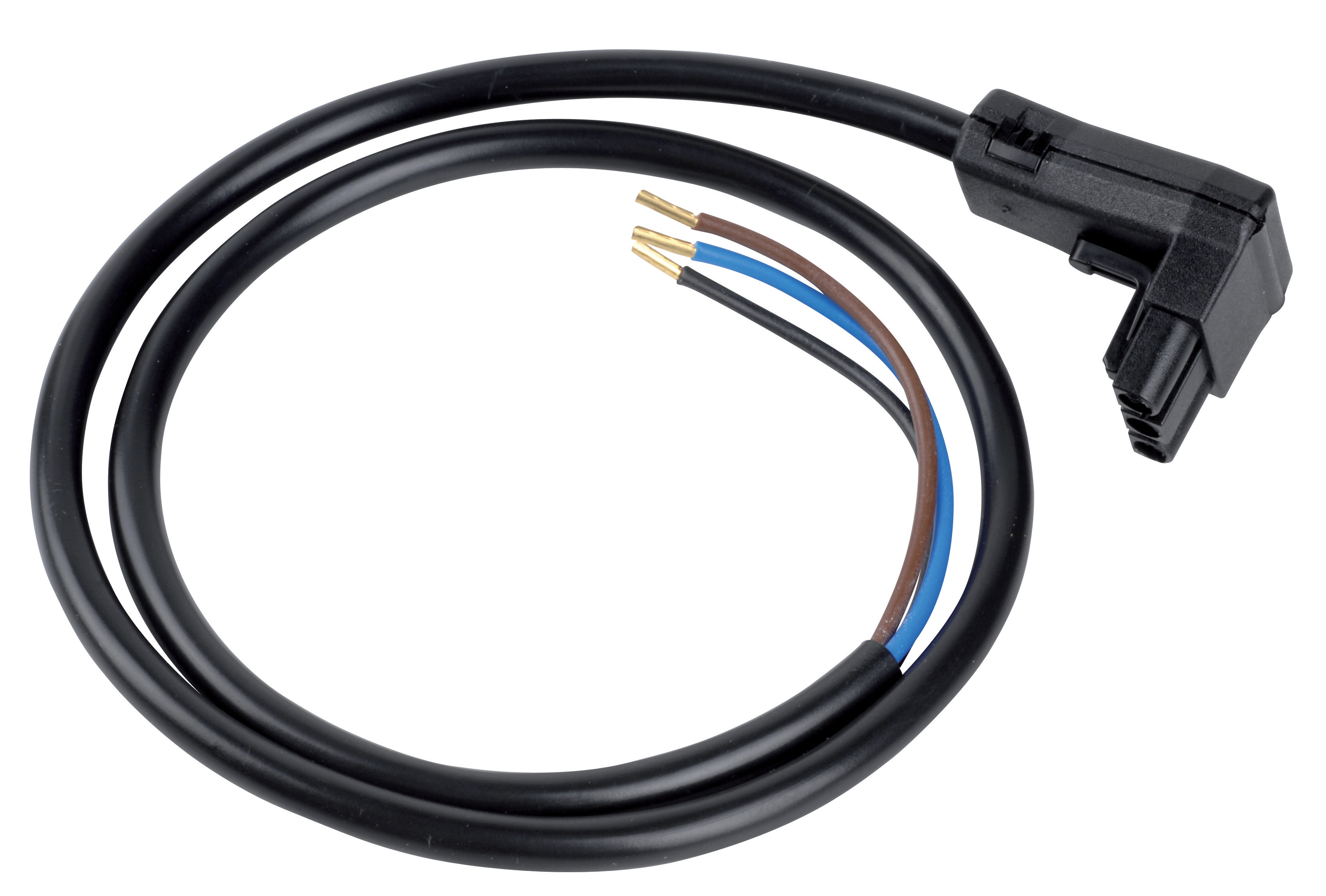
Because the Satronic DMG 970-N and Siemens LME 22 process flame signals differently, your test methodology changes. Satronic relays respond to infrared detection (used with the Satronic Cable for IRD10 series), while Siemens relays handle both ionization and flame rectification. When upgrading or retrofitting systems, test old and new relays side-by-side before full deployment to confirm compatibility.
Section 3: Solenoid Valve Response Time and Pressure Drop Validation
Solenoid valves control gas flow into burners. Poor response time increases ignition delay; excessive pressure drop reduces flame stability. Testing requires specific pressure measurement techniques.
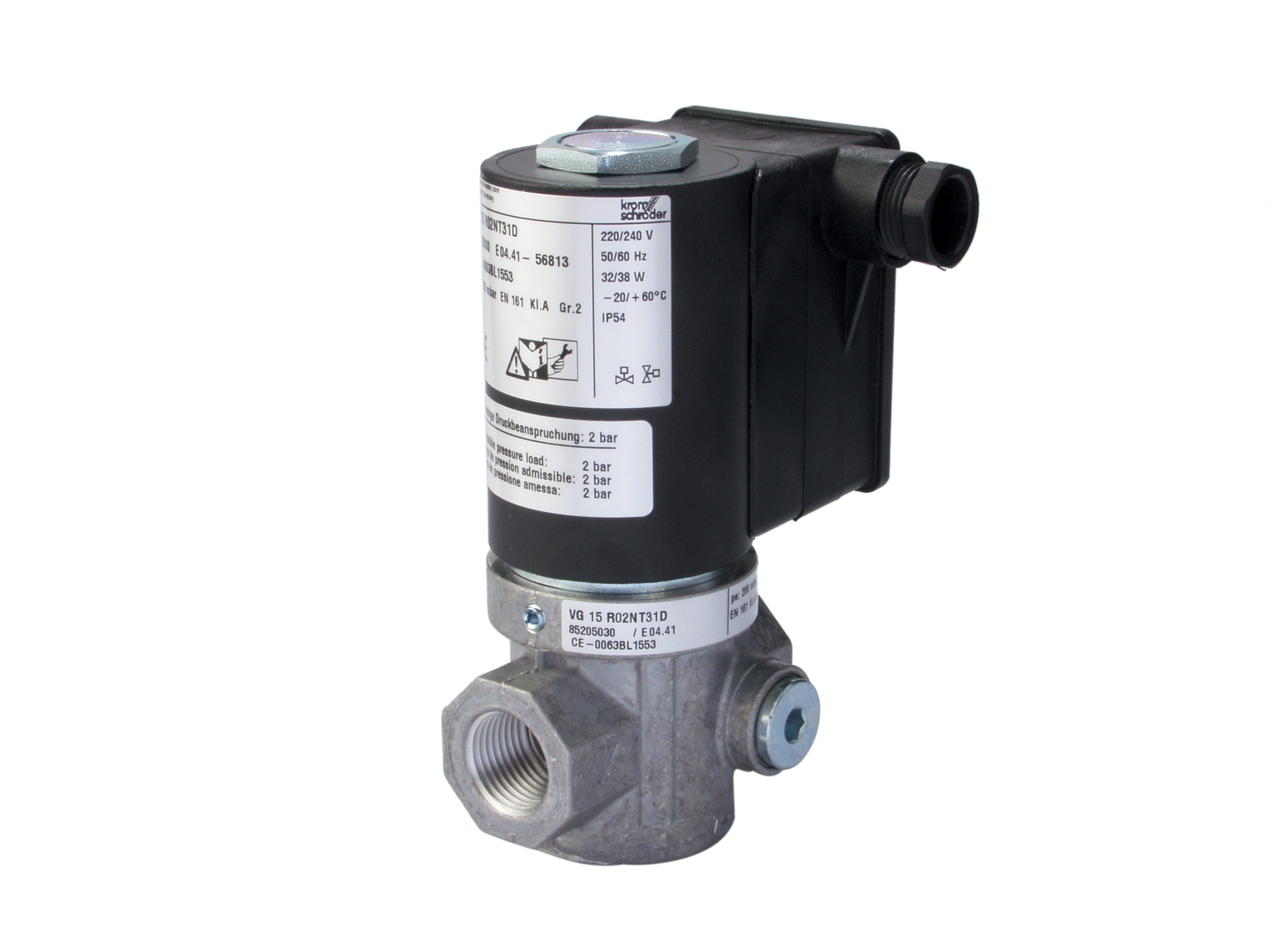
Testing the Kromschroder Fast Solenoid Valve
The Kromschroder Fast gas solenoid valve VAS 115R/NQ features LED blue control indication and is rated for maximum upstream pressure of 500 mbar. This "fast" designation means sub-200ms response times are critical for burner ignition systems.
1. Response time measurement: Connect the solenoid to a test rig with pressure gauges at inlet and outlet. Apply electrical signal and measure time from signal arrival to audible valve click. Professional technicians use oscilloscopes to capture this precisely. Typical range: 150-200ms for fast solenoids. Values exceeding 250ms indicate worn internal components or magnetic degradation.
2. Pressure drop under flow: Set upstream pressure to 500 mbar (rated maximum). Measure downstream pressure while gas flows at burner operating rate (typically 0.5-2 bar at main burner outlet). Calculate pressure drop: 500 mbar upstream minus downstream pressure. Compare against solenoid datasheet specifications. Excessive drop (>50 mbar above specification) indicates internal debris or coil fouling.
3. LED indication verification: The blue LED should illuminate when electrical signal is applied. Verify brightness is visible under facility lighting conditions. Dim LED indicates failing coil or low electrical signal.
4. Holding voltage confirmation: After initial energization, reduce supply voltage gradually while monitoring valve state. The valve should remain open until voltage drops below specified "holding voltage" (typically 70-80% of rated voltage). Valves that drop out prematurely indicate coil degradation.
Comparison with Control Box Solenoid Valves
The Sit Control box Sit 0579311 (which replaces 0577311) integrates solenoid valve functions internally. Testing this requires different approach:
- Integrated response testing: Cannot test solenoid valve response independently; must measure gas flow onset from electrical signal arrival at control box input
- Pressure signature analysis: Measure pressure pulsations during ignition sequence to identify timing issues within the integrated control logic
- Spark gap measurement: The control box features 2–4 mm spark gap. Measure actual gap using feeler gauge. Gaps exceeding 4mm require electrode adjustment before recommissioning.
The control box integrates multiple functions—ignition spark generation, gas valve control, and flame signal processing—making individual component testing impossible. If one function fails, the entire unit typically requires replacement, unlike modular systems where individual relays or solenoid valves can be swapped.
Section 4: Flame Detection Validation and Signal Quality Assessment
Flame detection systems must reliably distinguish between pilot flame, main flame, and no-flame conditions. Poor signal quality causes false lockouts or dangerous delayed shutdowns.
Testing Infrared Flame Detectors
The Satronic Cable for IRD10 series connects infrared detectors to control relays. These detectors operate across 800–1100 nm spectral range with peak sensitivity at 950 nm and support 15–150 Hz frequency response.
1. Optical element cleaning and inspection: Remove infrared detector element from burner housing. Inspect quartz window for soot, oil mist, or dust accumulation. Clean using lens paper and specified cleaning solution. Deposits reduce sensitivity by 20-50%. After cleaning, measure DC output voltage with no flame present—should be <0.5V. Main flame should produce 3-8V output depending on flame intensity and distance.
2. Spectral response verification: Professional test equipment includes flame simulators with tunable wavelength. Test detector response across 800-1000 nm range. Peak response should occur near 950 nm. Flat or shifted response indicates detector aging or optical element degradation.
3. Cable continuity and resistance: Measure resistance on all four poles of the IRD cable. Expect 0.1-0.5 ohms per cable length meter. Resistance exceeding 2 ohms indicates corrosion inside connectors. Measure voltage drop under signal conditions; should not exceed 0.5V at maximum flame signal.
4. Frequency response testing: Apply AC signal (simulating flame flicker) at 15 Hz and 150 Hz. Measure output amplitude. Response should remain within ±10% between these frequencies. Significant attenuation at high frequencies indicates coupling capacitor degradation in detector electronics.
Comparative Signal Quality Assessment
Different flame detector types require different validation approaches:
- Ionization detectors (used with Siemens relays) measure ionization current directly, producing DC output signals. Test by varying fuel gas composition and measuring current change—values should shift 20-40% as flame chemistry changes.
- Infrared detectors (used with Satronic relays) measure radiant intensity, producing relatively stable DC output. Test by applying temporary soot coating to detector window and confirming output drops 30-50% (then clean and verify recovery).
- Flame rod detectors (UV sensing) provide fastest response but are most prone to spurious signals from electrical arcing. Test by introducing non-flame electrical noise near detector and confirming it doesn't trigger false "flame detected" indications.
Choose detector type based on your fuel type and operating environment. Natural gas burners work well with any detector type. Oil burners require infrared detection. Dual-fuel systems often use flame rods for fastest response.
Documentation and Trending
Record all test measurements in a maintenance log. For each control system, establish baseline values during commissioning. Compare each maintenance inspection against baseline:
- Response times increasing >10%: Schedule component replacement
- Pressure drops increasing >20%: Clean or replace solenoid valves
- Flame detector voltage output decreasing >15%: Clean detector or plan replacement
- Insulation resistance dropping below 50 MΩ: Replace component immediately to avoid electrical hazards
3G Electric's 35 years of experience serving Singapore's industrial sector demonstrates that systematic diagnostic testing prevents 70-80% of unexpected burner control failures. Reactive maintenance—replacing components only after failure—costs 3-5x more than preventive testing and replacement on schedule.
Best Practices Summary
Effective Controls & Safety diagnostic testing requires:
1. Component-specific procedures: Satronic, Siemens, Sit, and Kromschroder systems each need tailored testing approaches
2. Baseline documentation: Establish known-good measurements during commissioning for meaningful trend analysis
3. Calibrated equipment: Invest in properly maintained multimeters, pressure gauges, and specialized analyzers
4. Regular scheduling: Test systems quarterly in normal operation, monthly in high-utilization facilities
5. Trending and prediction: Use measurement history to predict failures 4-12 weeks before they occur
By implementing these diagnostic procedures, industrial professionals across Singapore can maintain burner system reliability, reduce downtime, and ensure continuous safe operation.