Controls & Safety: Optimizing Solenoid Valve and Relay Performance in Burner Systems
For three decades, 3G Electric has supplied industrial control and safety components to plant operations worldwide. One of the most overlooked performance variables in burner system design is the synchronization between relay switching speed and solenoid valve response time. This mismatch directly impacts ignition reliability, fuel consumption efficiency, and safety margins. Plant managers need practical guidance on how these two critical components interact, and how to select them as an integrated system rather than independent parts.
Understanding Response Time Specifications
Relay switching speed and solenoid valve response time operate on different timescales, creating a design challenge that many specifiers misunderstand. A control relay like the Satronic DMG 970-N MOD.01 switches electrical contacts in 10–50 milliseconds, depending on the relay design and power supply frequency (50Hz or 60Hz). This is the time it takes for the relay coil to energize and physically move the contact arm.
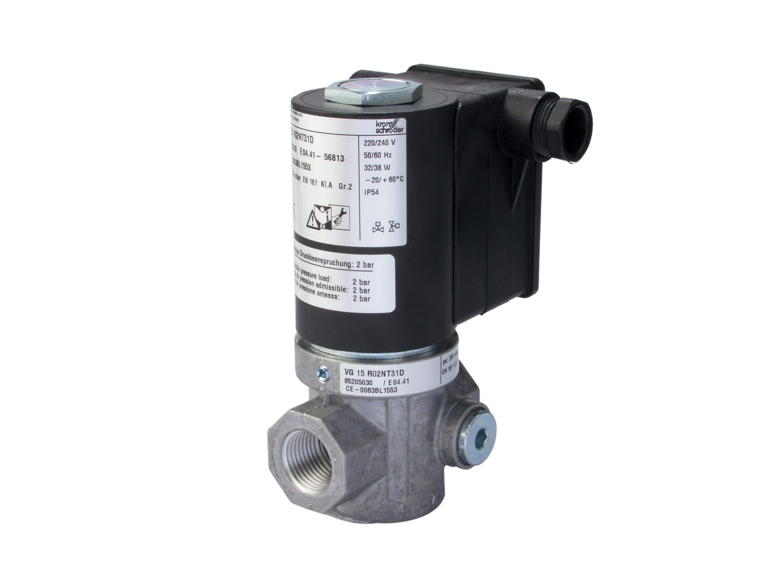
Solenoid valves, however, operate on a completely different principle. The Kromschroder VAS 115R/NQ is a fast gas solenoid valve rated for burner applications, yet even fast solenoids require 80–200 milliseconds to achieve full stroke and reach maximum flow. This means there is always a delay—sometimes 150+ milliseconds—between the moment your relay signals the solenoid and when gas actually reaches the burner flame head.
For plant managers, the practical implication is clear: a relay cannot "open" fuel to a burner instantly. The solenoid valve is the actual bottleneck in your ignition sequence. Selecting a high-speed relay paired with a sluggish solenoid creates a false sense of control system responsiveness.
Performance Comparison: Relay-Dominated vs. Valve-Limited Systems
There are three common architectural approaches in industrial burner control:
1. Relay-First Architecture
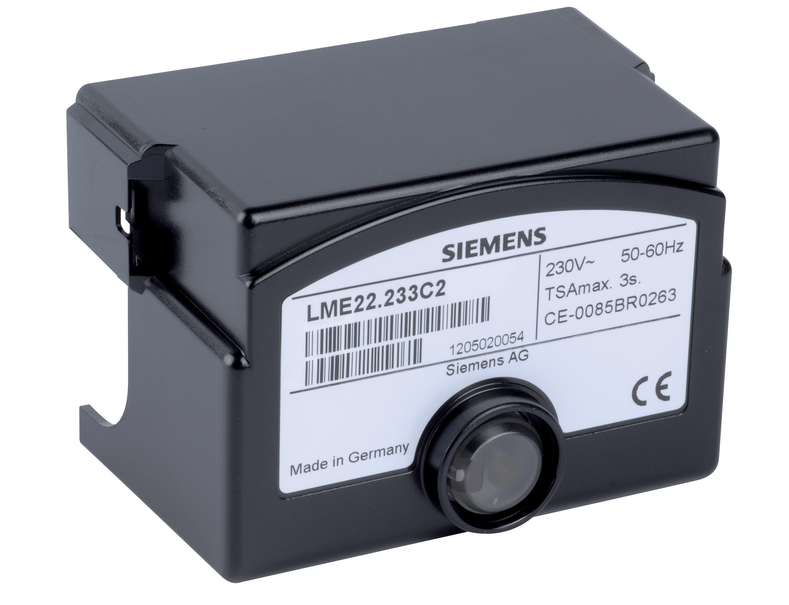
Relays like the Sit 0579311 DBC or Siemens LME 22 233C2 are the primary control element. They switch power to the solenoid valve and monitor flame detection circuits. Both relays offer sub-50 millisecond switching, but their actual system response is determined by the solenoid valve they control. If the solenoid takes 150 ms to open, the system response is 150 ms, not 50 ms. Plant managers often specify high-performance relays when the real bottleneck is valve lag.
2. Solenoid-Limited Architecture
This is reality for 95% of industrial burners. The Kromschroder VAS 115R/NQ represents a fast solenoid class with response times under 120 ms. However, upstream pressure, coil temperature, and valve age all affect actual response. A solenoid rated at 100 ms at ideal conditions may perform at 180 ms in a cold ambient or high-altitude installation. For plants operating at elevation or in harsh environments, solenoid selection becomes the critical path item.
3. Integrated Control Box Architecture
Devices like the Sit 0579311 combine relay switching and ignition timing in a single unit. These integrated systems can synchronize internal timing to account for solenoid lag, improving overall system responsiveness. The tradeoff is reduced flexibility in component selection.
Flame Detection and Response Time Interdependence
Response time becomes even more critical when paired with flame detection systems. The Satronic IRD 810/820 infrared flame detector cable operates at 15–150 Hz frequency, meaning it samples the flame 15 to 150 times per second. If your solenoid takes 200 ms to respond to a "flame lost" signal, the detector may sample the flame status 3 to 30 times before fuel is actually shut off.
Plant managers must understand this timing hierarchy:
- Flame Detector Frequency: 6.6–66 ms per sample (at 150 Hz to 15 Hz)
- Relay Switch Time: 10–50 ms
- Solenoid Response Time: 80–200 ms
- System Stabilization: 200–400 ms (time for fuel pressure and flame to stabilize)
If your flame detector cycles at 150 Hz (6.6 ms per sample) but your solenoid valve takes 200 ms to close, you are essentially running on a 200 ms safety window. A 50 ms faster relay does not improve this margin at all.
Practical Selection Criteria for Plant Managers
Application 1: Standard Industrial Heating
For most plant heating and steam generation, a relay like the Siemens LME 22 233C2 paired with a standard solenoid (150–180 ms response) is acceptable. The system response is 180–250 ms total. This is adequate for most industrial applications where ignition happens once per startup cycle. Cost per unit: moderate. Maintenance burden: low.
Application 2: High-Frequency Modulation or Repetitive Ignition
For applications requiring multiple ignition attempts, rapid fuel cutoff, or modulating burner control, upgrade to the Kromschroder VAS 115R/NQ fast solenoid (100–120 ms) paired with the Satronic DMG 970-N MOD.01 relay (25 ms switching). Total system response: 125–145 ms. This combination is necessary for safety-critical applications with frequent flame-out events. Cost: 30–40% premium. Maintenance: monitor solenoid coil condition annually.
Application 3: Critical Process with Redundancy
Where safety margins are non-negotiable (high-pressure steam, explosion-hazard environments), use an integrated control unit like the Sit 0579311 DBC with built-in timing logic. These account for solenoid lag internally and provide predictable, synchronized response. Cost: highest. Maintenance: requires trained technicians for diagnostics.
Real-World Performance Data
3G Electric has observed field data across thousands of installations globally. Here are key findings:
- Component age impact: A solenoid valve at 5 years old shows 15–25% longer response time than new. Many plant managers do not budget for preventive solenoid replacement.
- Ambient temperature effect: Every 10°C drop below 10°C increases solenoid response time by approximately 5–8%. Cold-climate installations need faster valves by design.
- Pressure variation: Upstream pressure swings of ±50 mbar can shift solenoid response by ±20 ms. Plants with variable fuel supply (backup generators, multiple boiler banks) should specify pressure-compensated solenoids.
- Relay contact wear: Relay contacts degrade over 100,000+ cycles. Most industrial relays are not replaced proactively; instead, response time gradually increases from 20 ms to 60–80 ms over 8–12 years.
Diagnostic Testing and Validation Protocol
Plant managers should implement a simple field validation:
1. Baseline Test: At commissioning, measure actual solenoid response using a pressure transducer on the gas outlet line. Record the time from relay energization to 90% pressure rise. Expected: 100–180 ms for standard equipment.
2. Annual Verification: Repeat the test during annual maintenance. Expect 5–15% increase in response time due to coil temperature cycling and contact wear.
3. Trending: Track response time over 5 years. If response time increases by >40% from baseline, schedule component replacement before safety margins erode.
4. Comparative Testing: If upgrading from Sit 0579311 to Satronic DMG 970-N MOD.01, measure before and after. Document the actual system-level improvement, not just relay specifications.
This data-driven approach replaces guesswork with measurable performance and justifies capital expenditure to finance and safety departments.
Conclusion: Integration Over Individual Specifications
The most common mistake in burner control system selection is optimizing each component independently. A plant manager might select the fastest available relay without verifying that it is properly matched to the solenoid valve response time. The result is overspecified equipment, higher costs, and no actual safety benefit.
Working with 3G Electric's 35+ years of industrial equipment experience, plant managers should request complete system timing specifications—not just individual component datasheets. Ask for total system response time from flame-out signal to fuel shutoff, measured under actual operating conditions.
The components featured in this analysis—Satronic DMG 970-N MOD.01, Sit 0579311 DBC, Kromschroder VAS 115R/NQ, Siemens LME 22 233C2, and Satronic IRD 810/820—represent proven industrial-grade solutions. The key is selecting them as an integrated system, not as isolated parts. This approach reduces safety risk, improves reliability, and delivers measurable operational benefit.