Controls & Safety: Pressure Drop Analysis and Flow Rate Verification for Industrial Gas Control Blocks
With over 35 years of experience as a distributor of industrial equipment, 3G Electric has supported thousands of installations across Southeast Asia. One of the most overlooked aspects of burner system design is the precise verification of pressure drop and flow rate characteristics through gas control blocks. This technical explainer addresses the practical methods industrial professionals use to validate system performance, ensure compliance with manufacturer specifications, and prevent operational failures in Singapore's demanding industrial environments.
Understanding Pressure Drop Fundamentals in Gas Control Blocks
Pressure drop represents the differential pressure required to maintain a specific gas flow rate through a control device. Every component in a gas delivery system—regulators, solenoid valves, safety blocks, and restrictors—introduces measurable resistance to flow. The total system pressure drop must be calculated during design and verified during commissioning to ensure the burner receives adequate fuel at the correct pressure.
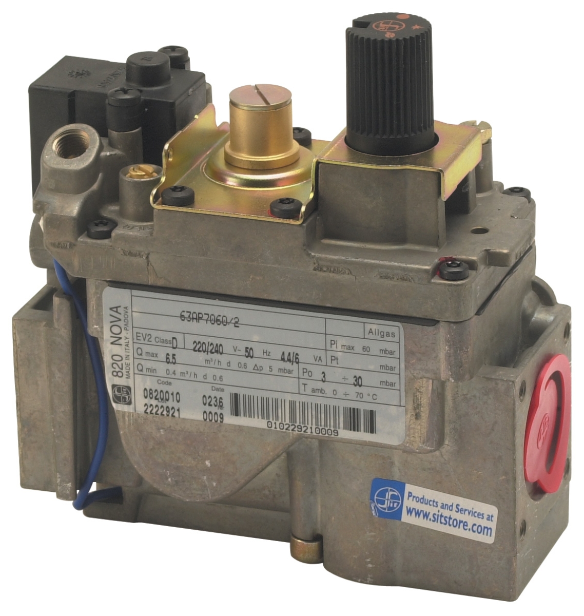
For example, the SIT Tandem gas block 0837013 specifies a pressure drop of 5 mbar at its maximum flow rate of 4.8 m³/h. This means that if your inlet pressure is 50 mbar, the outlet pressure will be approximately 45 mbar under full-load conditions. This 5 mbar loss is acceptable in most applications, but it becomes critical when your system operates near the lower pressure threshold (7 mbar minimum for this device) or when multiple components are installed in series.
Pressure drop follows the relationship: ΔP = k × (v²), where ΔP is pressure drop, k is the component resistance factor, and v is flow velocity. This non-linear relationship means that doubling flow rate will increase pressure drop approximately fourfold. Understanding this principle helps prevent undersizing gas control blocks, which can result in insufficient fuel delivery during peak demand cycles.
In Singapore's hot, humid climate, pressure measurement accuracy is particularly important. Humidity affects gas density and flow characteristics slightly; therefore, pressure gauges should be calibrated regularly and installed at standardized measurement points (inlet and outlet, 30 cm from the component). Use differential pressure gauges (manometers) with 0-100 mbar range for accuracy in low-pressure systems typical of domestic and light commercial burners.
Flow Rate Verification Methods and Measurement Protocols
Flow rate verification ensures that a gas control block delivers the design fuel consumption rate at the specified operating pressure. Three primary methods are used in the field: volumetric measurement (soap bubble method), gravimetric measurement (weight-based), and indirect calculation from burner performance parameters.
Volumetric Measurement (Soap Bubble Method)
The soap bubble method is the most practical for field verification. Connect a flexible hose to the gas outlet and insert it into a graduated cylinder containing soapy water. Record the time required for the bubble to travel a known volume (typically 1 liter). Calculate flow rate as: Flow (m³/h) = (Volume in liters / Time in seconds) × 3.6.
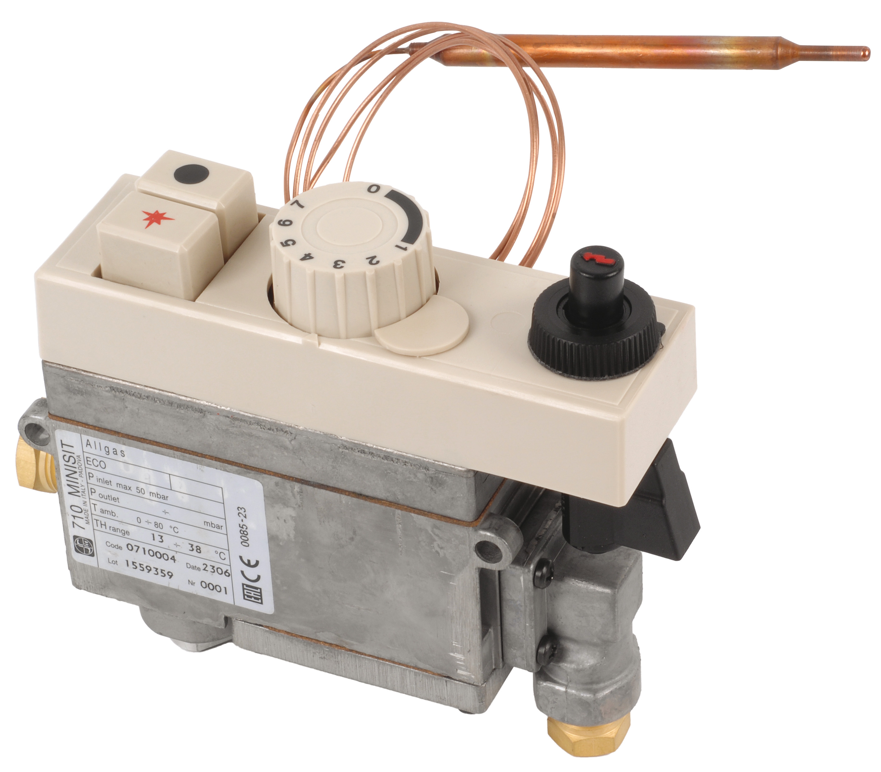
For the SIT Minisit gas block 0710004, which handles flows up to 3.9 m³/h, a typical test would verify flow at the control block's outlet under representative operating pressure (typically 20 mbar). Allow 2-3 minutes for system stabilization before starting measurements. Take minimum three consecutive readings and average the results. Acceptable variance is ±5% of the design specification.
Gravimetric Measurement
For higher accuracy, especially in commissioning new installations, use a digital scale to measure gas consumption over a timed interval. Connect the outlet to a collection vessel on a calibrated scale. Record the mass increase over 60 seconds, then convert to volumetric flow using standard gas density tables (typically 0.68–0.75 kg/m³ for natural gas at sea level in Singapore).
Calculation: Flow (m³/h) = (Mass gain in kg / Gas density in kg/m³) / (Time in hours)
This method is more accurate than volumetric measurement and accounts for pressure and temperature variations during the test.
Indirect Calculation from Burner Performance
When direct measurement is impractical, flow rate can be verified indirectly by measuring burner output and working backward. Record the fuel pressure at the burner inlet, measure the exhaust temperature rise and flue gas composition (CO₂, O₂), then calculate fuel consumption using combustion balance equations. Compare the calculated value against the design specification. This method requires analytical equipment but is valuable for troubleshooting existing installations.
Selecting Gas Control Blocks Based on Pressure and Flow Requirements
Correct selection of a gas control block requires detailed analysis of your system's pressure range, maximum flow rate, and duty cycle. Under-specification (selecting a block rated below your actual requirement) causes excessive pressure drop and inadequate fuel delivery. Over-specification reduces control precision and may cause unnecessary pressure regulation losses.
Start by determining your maximum fuel consumption rate in m³/h. For example, a 100 kW burner typically consumes approximately 10–12 m³/h of natural gas. Your control block must be rated for at least this flow rate with acceptable pressure drop.
Next, identify your operating pressure range. The SIT Tandem gas block 0837013 operates from 7 to 50 mbar with 5 mbar drop at full flow. If your system pressure varies from 15 to 35 mbar, this block is suitable because outlet pressure will range from 10 to 30 mbar, remaining within acceptable burner input ranges. However, if your system operates at 8 mbar inlet (near the minimum), the outlet drops to 3 mbar—insufficient for stable burner operation. In this scenario, select a lower-capacity block with reduced pressure drop, such as the SIT Minisit 0710004 (3.9 m³/h, suitable for smaller burners with tighter pressure control requirements).
Consider the application's load profile. Continuous operation at maximum capacity favors a larger control block (lower pressure drop, less heat generation). Applications with frequent on-off cycling or modulating burners benefit from multifunctional blocks like the SIT Sigma 0845063, which provides servo-assisted pressure regulation for smooth load transitions and reduced control overshooting.
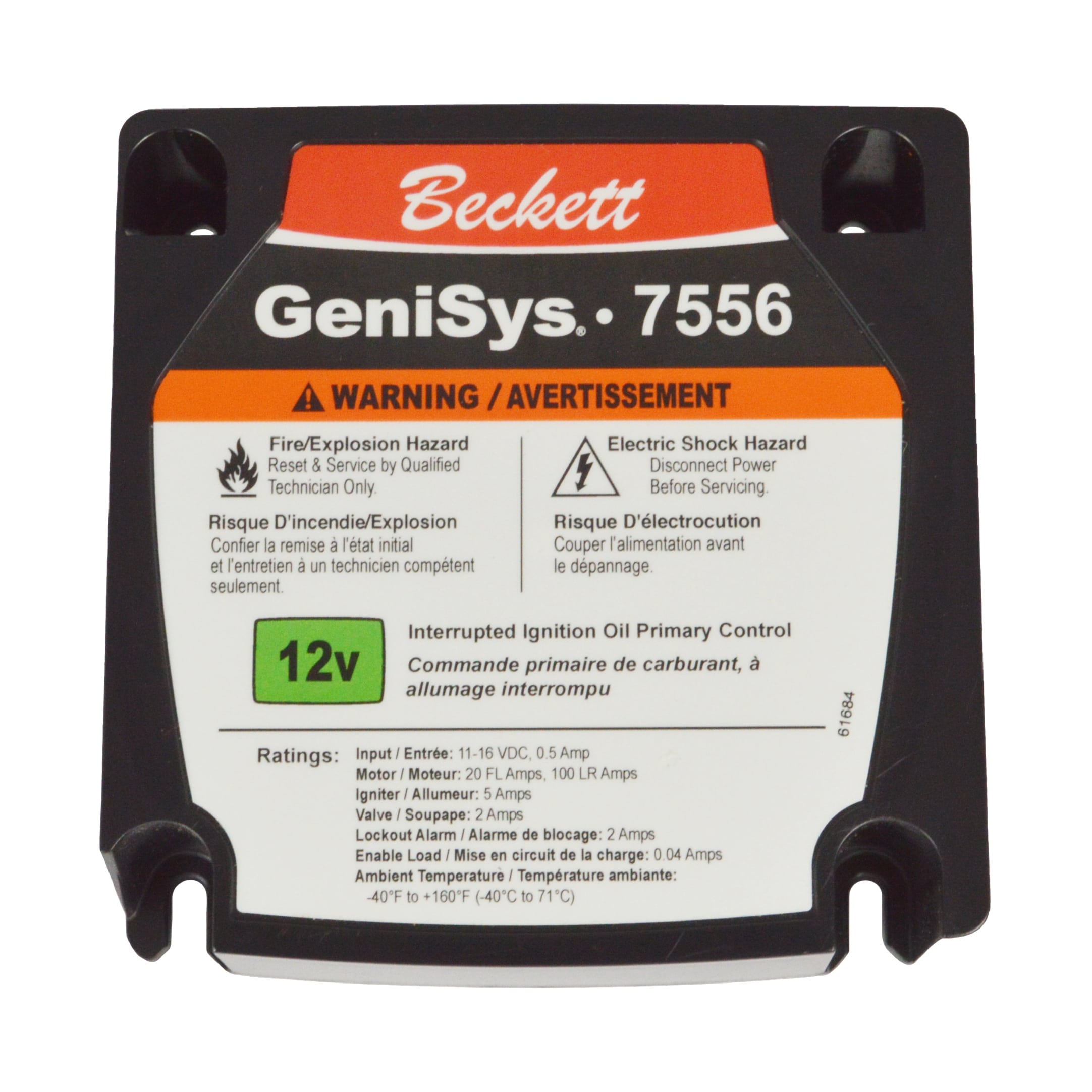
For applications using oil burners, such as mobile heating equipment, the Beckett GeniSys® 7556 12V Oil Burner Control provides integrated safety interlock and programmable purge timing, eliminating the need for external pressure monitoring devices. This integrated approach reduces installation complexity and improves reliability in challenging environments.
For electronic control applications, the SIT control box 0577211 integrates microprocessor-based flame detection and burner sequencing. This device requires careful commissioning of the spark gap (2–4 mm) and verification of the 230 Vac alarm output (1 A capacity). Pressure measurement during commissioning must account for the electronic control's response characteristics; allow additional stabilization time when switching between manual and electronic regulation.
Commissioning Verification and Performance Documentation
During commissioning, create a detailed pressure and flow rate profile across your entire gas delivery system. Record measurements at: inlet to the regulator/control block, outlet from the control block, inlet to the burner, and at intermediate points if multiple components are in series.
Document baseline pressure drop data under three load conditions: minimum, nominal, and maximum burner demand. Minimum demand (typically 30% of maximum) verifies that the control block maintains adequate outlet pressure even at reduced load—critical for flame stability. Nominal demand (typically 70–80% of rated capacity) represents normal operating conditions. Maximum demand verifies the block can deliver full fuel supply without excessive pressure loss.
Create a commissioning report that includes: (1) control block manufacturer and model, (2) rated flow capacity and operating pressure range, (3) measured inlet and outlet pressures at each load point, (4) calculated pressure drop values, (5) measured volumetric flow rate (m³/h) at nominal load, (6) burner combustion efficiency and excess air percentage, and (7) confirmation that all parameters fall within manufacturer specifications.
Maintain this documentation for your maintenance records and regulatory compliance file. In Singapore, periodic inspections under the Gas (Amendment) Regulations require evidence that gas control equipment continues to operate within specified parameters. Regular verification (typically annually) helps identify gradual performance degradation—such as increased pressure drop indicating solenoid valve wear or control block fouling—before safety issues develop.
When performance drifts beyond acceptable limits, systematic troubleshooting begins with isolating which component contributes excess pressure drop. Block off downstream components and re-measure; if pressure drop normalizes, the downstream device requires maintenance or replacement. If pressure drop remains elevated, the control block itself requires inspection or replacement.
Integration with Safety Interlocking Systems
Pressure monitoring is a critical safety function. Many control systems include differential pressure switches that trigger shutdowns if outlet pressure falls below minimum safe limits. Verify that your pressure monitoring points are installed correctly: inlet tap at the control block inlet (not the regulator inlet, to isolate the block's contribution), outlet tap at the block outlet (before any downstream restrictions), and connections made via 6 mm copper tubing per EN 1254-1.
For systems using the SIT Sigma 0845063 with servo-assisted regulation, pressure monitoring must account for the servo pilot pressure (typically 3–4 mbar above main outlet pressure). Failure to account for this offset can cause false low-pressure alarms. Consult manufacturer documentation to confirm the correct differential pressure switch setting.
Pressure testing should also verify that safety solenoid valves respond correctly to loss-of-pressure signals. A typical test involves blocking the outlet and recording the time to shutdown; this should occur within 2–3 seconds to meet safety standards. Document this response time in your commissioning report.
Conclusion
Pressure drop and flow rate verification represent the foundation of reliable, safe burner control system operation. By mastering these measurement protocols and applying them systematically during design, commissioning, and maintenance, industrial professionals in Singapore can prevent costly failures, ensure compliance with safety regulations, and optimize fuel efficiency.
3G Electric's technical team has supported industrial installations across Southeast Asia for over 35 years, providing equipment selection guidance, commissioning support, and maintenance expertise. Whether you are specifying a SIT Minisit for compact applications, upgrading to a SIT Tandem for high-capacity systems, or integrating advanced electronic controls like the SIT control box or Beckett GeniSys oil burner control, our team can guide you through proper pressure and flow verification to ensure optimal performance.