Understanding Controls & Safety Through Pressure Regulation Architecture
Controls & Safety in industrial burner systems extends far beyond flame detection and electrical interlocking—it encompasses the precise regulation of gas or oil flow under dynamic operating conditions. Pressure regulation is the mechanical and electronic backbone that maintains combustion stability, prevents fuel starvation during peak loads, and protects downstream components from over-pressurization. In Southeast Asian industrial facilities where ambient temperatures, load fluctuations, and fuel supply inconsistencies are common operational realities, sophisticated pressure management directly impacts equipment longevity and safety compliance.
3G Electric has distributed industrial burner control components for over 35 years, and our technical teams have observed that approximately 60% of field failures in burner systems stem not from ignition or flame detection faults, but from inadequate or degraded pressure regulation. Understanding how modern gas blocks like the SIT Sigma 0845063 integrate servo-assisted pressure regulation with solenoid valve sequencing is essential for specifying robust Controls & Safety architectures.
Servo-Assisted Pressure Regulation and Adaptive Flow Control
How Servo-Assisted Systems Maintain Combustion Stability
Traditional spring-loaded pressure regulators rely on mechanical feedback alone—as fuel demand increases, spring compression changes, affecting outlet pressure. Servo-assisted pressure regulation adds an electronic control loop that actively modulates a pilot solenoid valve, allowing the main regulator to maintain constant downstream pressure (typically 5–50 mbar) regardless of inlet fluctuations or load variations.
The SIT Sigma 0845063 gas block demonstrates this principle: its dual solenoid valve architecture enables the main valve to receive continuous pilot pressure adjustment, ensuring that burner fuel flow remains proportional to ignition demand rather than inlet pressure volatility. In Southeast Asian industrial environments where utility gas pressure can fluctuate by ±10 mbar due to peak-demand periods, this active regulation prevents the combustion instability that would otherwise trigger flame-out alarms or unsafe flame characteristics.
Pressure Drop Budget and System Design
When specifying gas control blocks, engineers must account for cumulative pressure drops across the entire fuel train:
- Inlet filter: 0.5–1.0 mbar
- Pressure regulator: 2–5 mbar (typical)
- Solenoid valve coil: 1–2 mbar
- Burner nozzle/orifice: 3–8 mbar
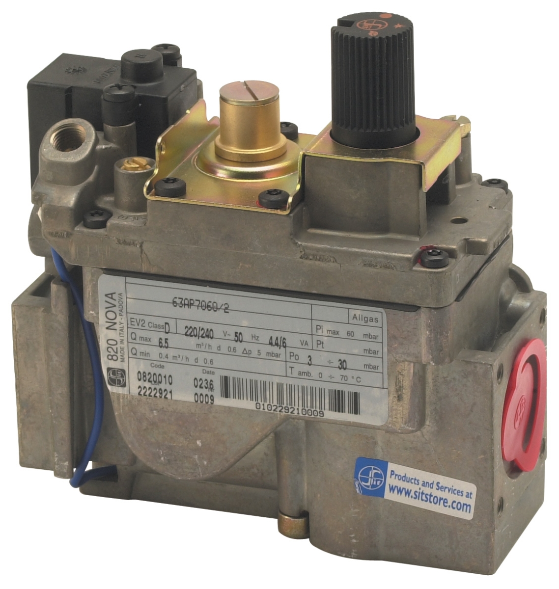
For example, the SIT Tandem 0837013 gas block delivers up to 4.8 m³/h flow rate with a nominal 5 mbar pressure drop across its main regulation stage. When integrated into a system where inlet pressure is nominally 20 mbar, the available pressure at the burner is approximately 15 mbar—adequate for most atmospheric burners but insufficient for forced-draft applications. Proper pressure margin calculation ensures that load increases don't cause burner starvation.
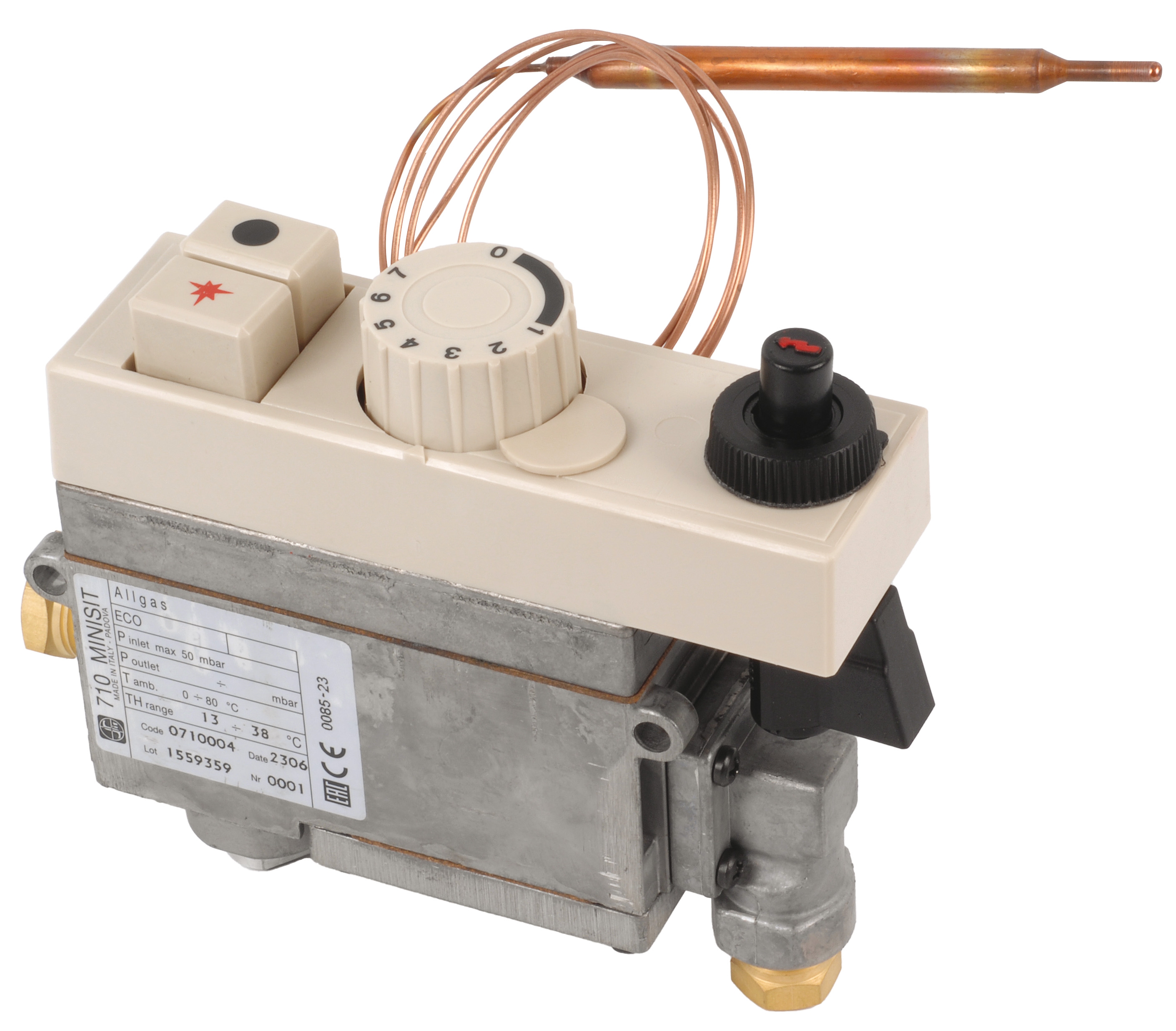
Engineers in Singapore and Malaysia frequently encounter this issue in retrofit applications where newer, higher-capacity burners are installed on older fuel distribution piping. A SIT Minisit 0710004 multifunction block, which handles flows to 3.9 m³/h and includes integrated thermoelectric safety shut-off, offers a lower pressure-drop alternative for moderate-capacity systems, but selection requires detailed load analysis.
Stepped Flow Control vs. Modulating Regulation: Operational Trade-Offs
Two-Stage (Stepped) Control Strategy
Many industrial heating systems operate in discrete capacity stages: low-fire (30–50% capacity) and high-fire (80–100% capacity). Stepped control uses separate solenoid valves for each stage, with the burner control system energizing them sequentially based on temperature demand.
Advantages:
- Simpler control logic and lower cost
- Fewer proportional valve components to maintain
- Well-suited to systems with stable loads and infrequent cycling
- Overshooting and hunting during load transitions
- Pressure relief valve venting when stepping down from high-fire
- Less efficient thermal response in facilities with variable occupancy or seasonal load swings
The SIT Tandem 0837013 is explicitly designed for stepped applications, offering two independent valve blocks within one manifold body, reducing installation footprint and valve count.
Continuous Modulating Control
Modulating systems use a proportional pilot valve that adjusts main-stage flow continuously across a wide operating range (typically 10–100% capacity). The burner control receives feedback from a combustion air pressure sensor or flue gas analyzer and continuously adjusts fuel flow to maintain optimal air/fuel ratio.
Advantages:
- Prevents overshooting and system hunting
- Delivers superior thermal efficiency (2–8% improvement typical)
- Reduces fuel wastage and emissions in variable-load facilities
- Lower acoustic signature (less cycling noise)
- Higher component cost and tuning complexity
- Requires reliable pressure or O₂ feedback sensors
- More frequent solenoid valve cycling can accelerate wear in high-cycling environments
For Southeast Asian applications with 24/7 industrial heating demands (textile dyeing, food processing, petrochemical preheating), modulating control's efficiency gains justify the investment, particularly in countries where fuel tariffs are rising or carbon-intensity regulations are tightening.
Adaptive Load Management and Dynamic Compensation
Temperature-Corrected Flow Scheduling
Ambient temperature variations in Southeast Asia (25–35 °C year-round in most regions) directly impact combustion air density and burner efficiency. Industrial burner control systems that incorporate temperature compensation adjust pressure setpoints or solenoid energization timing based on real-time ambient conditions, maintaining constant flame temperature and flame stability across seasonal swings.
For example, a boiler system operating at 50 mbar in winter air (cooler, denser) will experience different flame characteristics in summer ambient conditions if pressure is held constant. Advanced control blocks like the SIT Sigma 0845063 can integrate with temperature transmitters via the control relay module to dynamically adjust pilot solenoid duty cycle, effectively re-scheduling fuel delivery to compensate for air density shifts.
Pressure Offset and Load-Following Architecture
In cascading boiler banks or co-fired steam generation systems common in petrochemical and food-processing plants, master burner pressure setpoint must track secondary boiler demand. A load-following architecture uses a differential pressure transmitter across the fuel block outlet and the burner inlet to detect real-time demand, feeding back to the burner control system which then adjusts the pressure regulator pilot solenoid.
This closed-loop compensation prevents fuel starvation during sudden load spikes (e.g., when a parallel process line starts up) and avoids overpressurization during quick shutdowns. The SIT Sigma 0845063 230V 50Hz specification includes integral ports for differential pressure feedback, making it suitable for cascaded applications throughout Southeast Asian industrial parks.
Practical Commissioning and Field Verification
Pressure Testing and Flow Rate Validation
After installation, the fuel train must be tested at three critical points:
1. Inlet pressure (before regulator): Verify utility supply meets minimum inlet pressure requirement (typically 15–30 mbar for gas, 3–8 bar for oil)
2. Regulated outlet pressure (after main solenoid): Measure with burner energized at both low-fire and high-fire setpoints; must remain within ±2 mbar of target across the firing range
3. Burner inlet pressure (at flame nozzle): Confirm available pressure margin is at least 5 mbar above burner minimum requirement
Flow rate validation is conducted using an external gas meter or (for oil) by timed collection in a calibrated container. Measured flow should fall within ±3% of design specification. If flow exceeds specification at high-fire, either the inlet pressure is excessive or the regulator spring is weakened—both require corrective action before the system is released to operations.
Field Troubleshooting: Pressure Symptom Analysis
Symptom: Flame-out alarms during load ramp-up
- Likely cause: Insufficient inlet pressure or degraded pressure regulator
- Remedy: Confirm inlet pressure ≥20 mbar (or per equipment nameplate); clean or replace regulator filter element
- Likely cause: Pressure oscillation due to resonance in fuel piping or hunting in control loop
- Remedy: Increase regulator pilot spring tension (if adjustable); verify solenoid coil resistance matches control relay output (24V DC systems commonly fail due to voltage mismatch)
- Likely cause: Excessive pressure causing overfiring, or fuel type mismatch
- Remedy: Check fuel specification (pressure drop values vary for natural gas vs. propane); lower burner pressure in 1–2 mbar steps and retest flame color
Integration with Modern Control Relays and Safety Chains
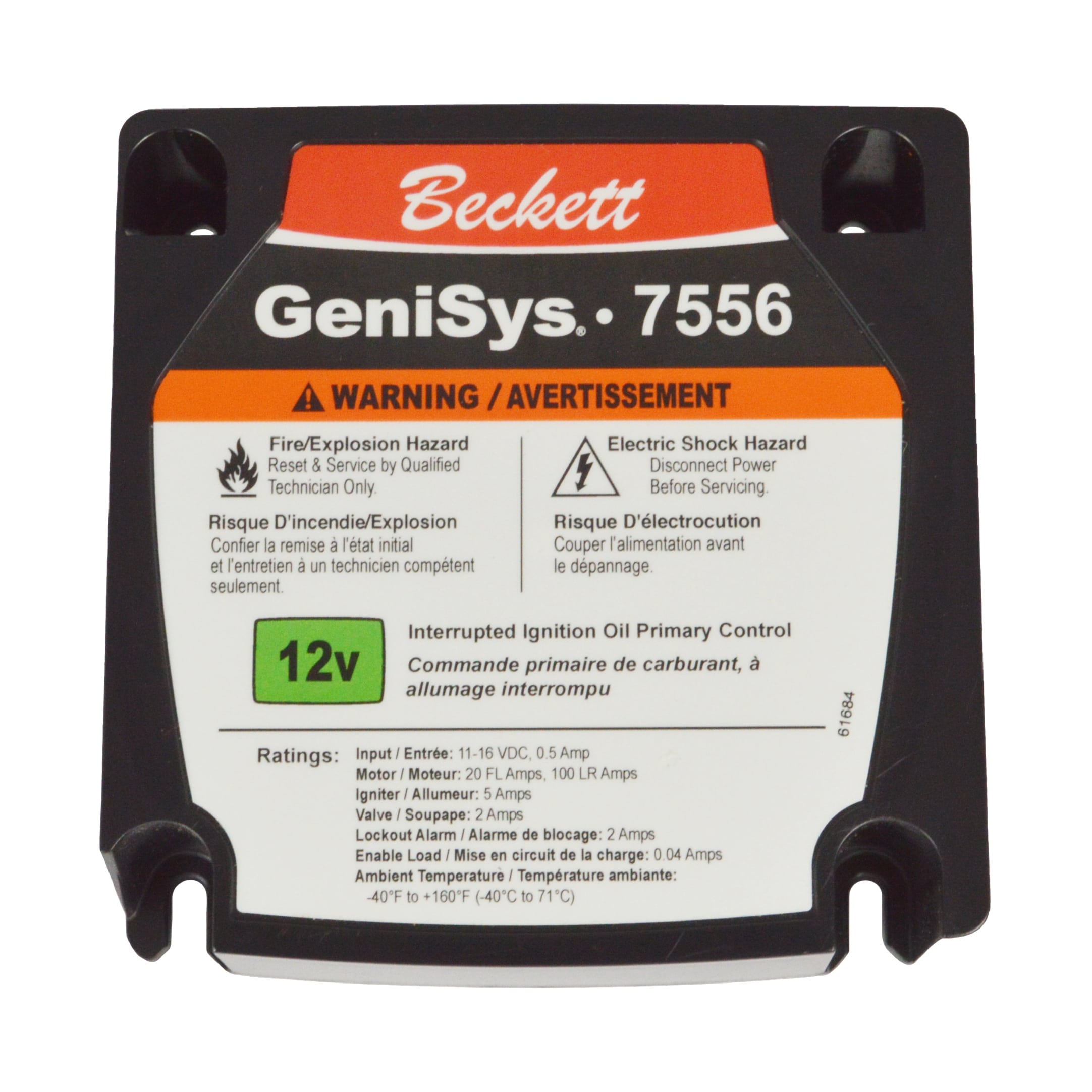
A complete Controls & Safety system pairs pressure regulation hardware with an intelligent control relay. The SIT 0577211 control box is a microprocessor-based burner control designed for gas appliances and boilers using natural or LPG gas, featuring 2–4 mm spark gap ignition and 230 Vac alarm output. This device can orchestrate solenoid valve sequencing, monitor pilot flame, and execute dynamic pressure adjustment commands to downstream gas blocks.
In a typical Southeast Asian HVAC boiler application:
1. Room thermostat signals demand to the 0577211 control box
2. Control box energizes the pilot solenoid in the SIT Tandem 0837013 or SIT Sigma 0845063 via a latching relay
3. After pilot flame confirmation (2–3 seconds), main stage solenoid is energized
4. Pressure regulator actively maintains 15–20 mbar outlet throughout the firing cycle
5. If flame is lost, control box de-energizes all solenoids and enters lockout; manual reset is required
This integration ensures that pressure regulation operates within a validated safety envelope—pressure adjustments only occur while flame is proven, and catastrophic overpressurization is prevented by the solenoid valve de-energization failsafe.
Regional Considerations for Southeast Asian Industrial Plants
Southeast Asian industrial facilities face unique pressure regulation challenges:
- Inconsistent utility gas quality: Varying moisture content and trace contaminants require more frequent filter maintenance; consider dual-element filter housings with bypass valves
- High ambient humidity: Condensation in fuel lines reduces regulator stability; specify vapor-sealed pilot pressure ports where possible
- Extended equipment runtime: 24/7 boiler operation in textile dyeing, palm oil processing, and food manufacturing demands regulators with low hysteresis and drift; servo-assisted designs significantly outperform spring-only designs over 10,000+ operating hours
- Limited maintenance windows: Modular block design (like the SIT Tandem) allows single-block replacement during brief shutdowns rather than complete fuel train servicing
3G Electric's regional support teams have found that specifying one pressure regulation block too low in capacity—then oversizing the burner downstream—is a common cost-optimization mistake that leads to chronic flame instability. Proper margin calculation and load profiling at commissioning time prevents costly troubleshooting cycles later.