Controls & Safety: The Foundation of Reliable Industrial Operations
Controls & Safety in modern industrial plants means far more than flipping switches. It's an integrated ecosystem where temperature sensors communicate with flame detectors, safety relays respond to pressure changes, and operators maintain visibility over every critical point. For plant managers in Singapore navigating tropical climates, varied equipment loads, and strict safety standards, understanding these interconnected systems is not optional—it's essential.
With over 35 years of experience as a global industrial equipment distributor, 3G Electric has supported thousands of plant managers in Southeast Asia through equipment selection, commissioning, and troubleshooting. This guide translates that experience into actionable strategies for your facility.
Section 1: Thermal Monitoring as Your First Line of Defense
Understanding Temperature Sensing in Industrial Burners
Temperature control is your plant's early warning system. When thermal monitoring fails, you don't just lose efficiency—you risk uncontrolled combustion, equipment damage, and safety incidents. The thermostat isn't a luxury feature; it's a critical control point.
Thermostat-based control systems work by sensing temperature at a specific point in your process (combustion chamber, heat exchanger outlet, or reaction vessel) and triggering relay contacts when temperature drifts outside your setpoint. This mechanical or electronic response can:
- Cut fuel supply to prevent overheating
- Signal alarms to alert operators of abnormal conditions
- Modulate burner intensity in proportional systems
- Initiate automatic shutdowns before damage occurs
Singapore's industrial environment presents specific thermal challenges. Ambient temperatures regularly exceed 32°C, humidity is high, and many facilities run continuous processes where temperature stability directly impacts product quality. A thermostat with poor repeatability or slow response time compounds these pressures.
Selecting the Right Thermostat for Your Application
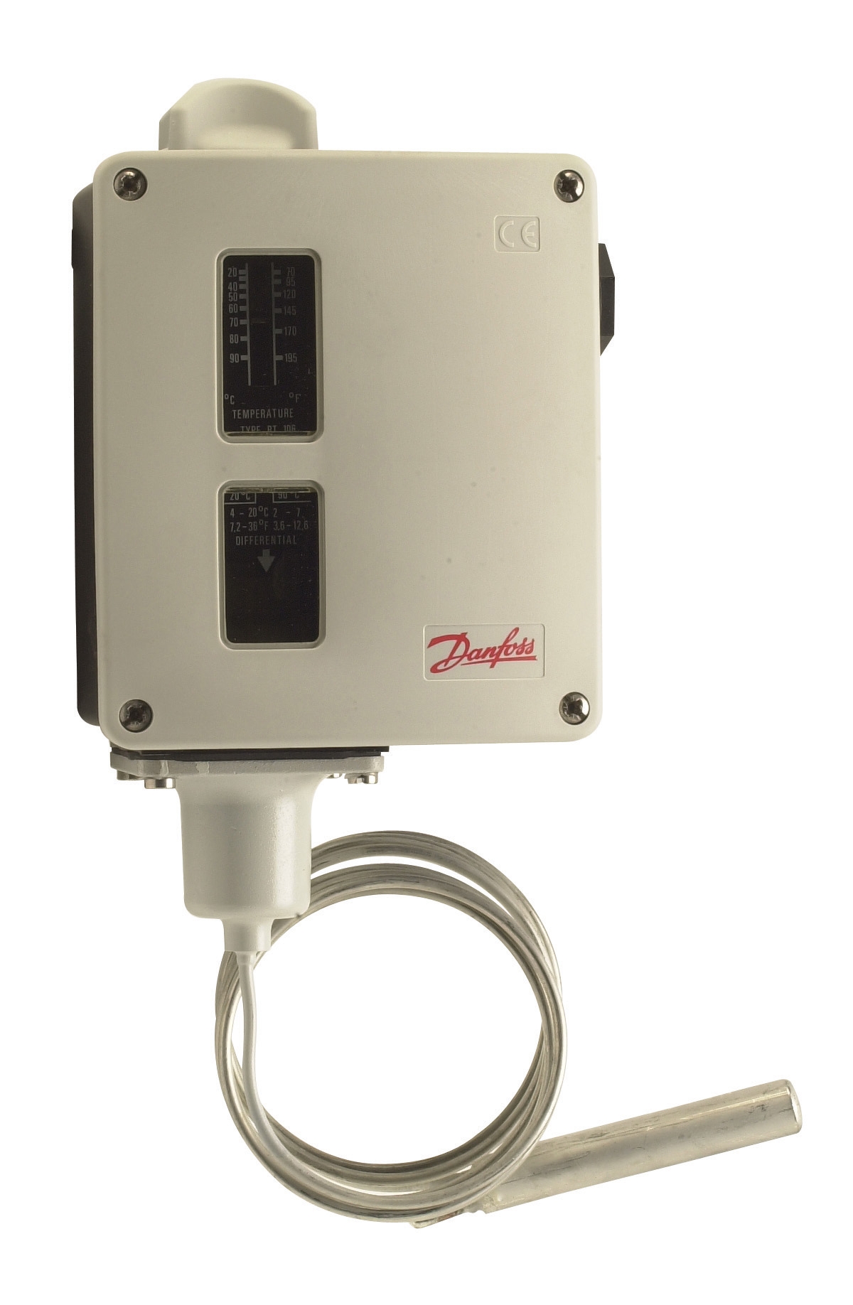
Not all thermostats perform equally. The Danfoss RT 124 offers bulb-actuated sensing ideal for direct immersion in process streams. Its single-pole changeover contact allows you to configure it for heating OR cooling applications—critical flexibility when you operate multiple thermal zones. The adjustable differential setting (typically 2-10°C) lets you fine-tune the trigger band to match your process stability requirements. A tight differential improves precision but increases cycling frequency; a wide differential reduces relay wear but sacrifices accuracy.
The Danfoss RT 107 provides similar functionality with universal single-pole changeover contact design, offering reliability across HVAC and industrial temperature regulation. Both models excel in harsh environments and integrate seamlessly with existing safety relay circuits.
Practical selection criteria for your facility:
- Sensing location: Direct immersion in fluid requires a bulb thermostat; surface mounting on pipes or ducts requires surface-mounted versions
- Temperature range: Verify the thermostat's operating range covers your process minimum and maximum plus 15% safety margin
- Response time: Faster-responding thermostats (filled with special fluids) prevent overshoot; slower units suit stable, low-cycling applications
- Contact rating: Match the thermostat's contact capacity (amperage and voltage) to your control circuit, with 20% safety margin
- Hysteresis/differential: Wider settings reduce relay chatter on marginal conditions; tighter settings maintain closer temperature control
Integration with Safety Relay Circuits
Your thermostat doesn't work alone. It must interface with safety-rated relay circuits that guarantee response even during component degradation. This layered approach—sensor + safety relay + final element (solenoid valve or motor contactor)—is why industrial Controls & Safety differs fundamentally from comfort HVAC.
When your thermostat contact opens or closes, the safety relay interprets that signal and energizes the shutdown solenoid only if other safety conditions are met. If flame detection fails, high-limit switches open, or pressure exceeds safe levels, the relay prevents fuel flow regardless of thermostat demand. This is not redundancy for its own sake—it's compliance with Singapore's manufacturing safety regulations and protection of your operation's reputation.
Section 2: Flame Detection and Burner Protection Integration
Why Flame Detection is Non-Negotiable in Modern Plants
Flame safety systems prevent the most catastrophic failure mode: unlit fuel accumulation followed by explosive ignition. In Singapore's industrial sector, flame detection is mandatory for any gas or oil burner exceeding 50 kW, and best practice for smaller installations.
Flame detectors sense the ultraviolet (UV) or infrared radiation emitted by active combustion. When flame is present, the detector sends a continuous signal to the amplifier. When flame is absent for more than 2-3 seconds (per manufacturing standards), the amplifier interprets this as a fault condition and de-energizes the ignition system and fuel solenoid.
The Honeywell Cell C 7044 A 1006 ultraviolet flame detector excels in detecting gas and oil flame signatures across the full visible spectrum. Its 1-inch tube size fits standard industrial burner configurations. UV detection responds extremely quickly (typically <100 milliseconds) and provides excellent immunity to ambient light interference—crucial in facilities with windows or outdoor installations.
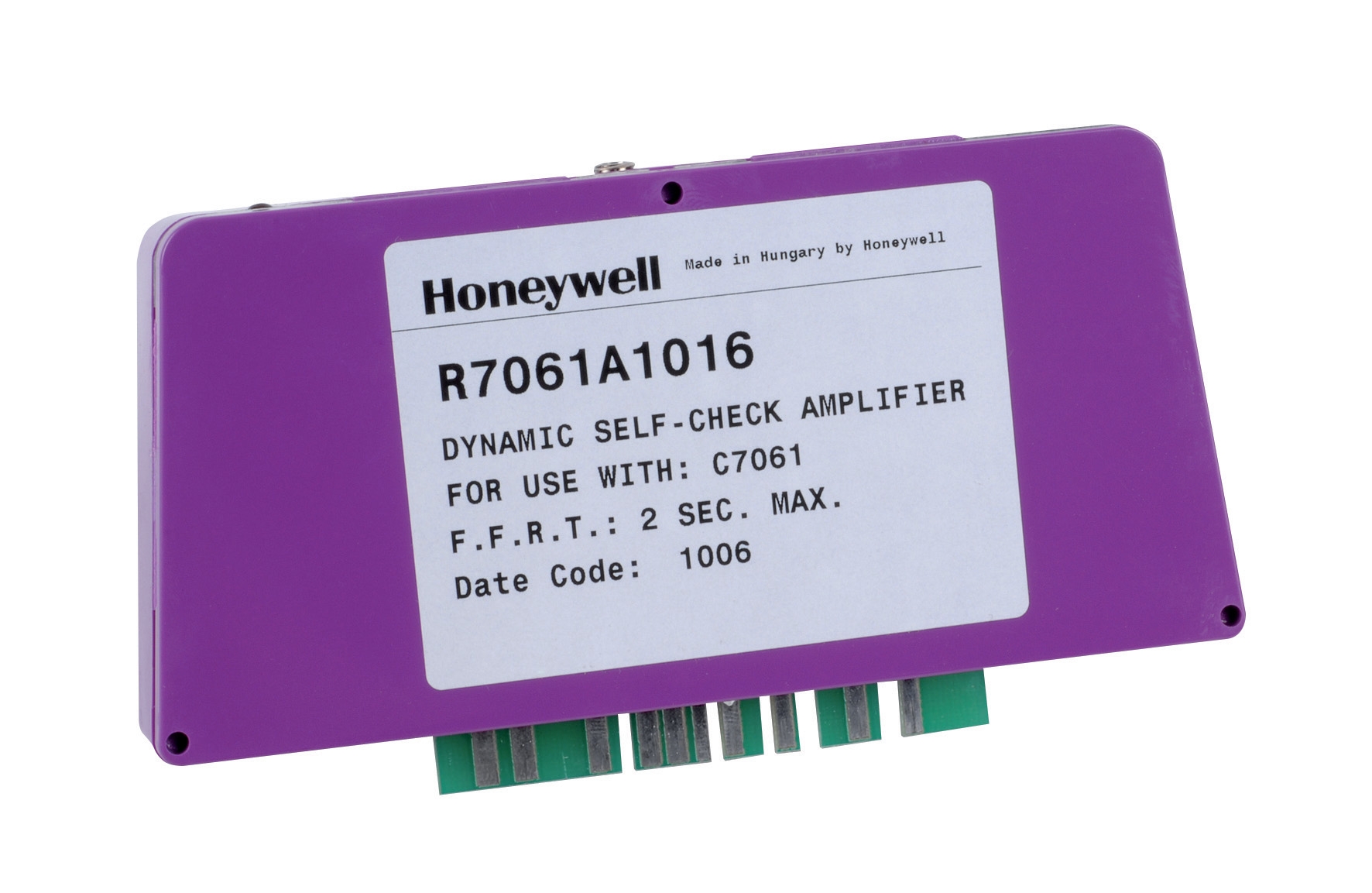
Paired with the Honeywell Amplifier R 7861 A 1026, your system gains intelligent processing. This amplifier tolerates -40°C to +60°C operation and 0.5g continuous vibration, meaning it performs reliably even in equipment rooms with active mechanical systems. The amplifier learns the noise signature of your specific flame over the first 10-15 seconds of burner startup (the commissioning phase) and then rejects any signal that doesn't match that learned pattern. This adaptive logic prevents false shutdowns from reflection, flicker, or electrical noise.
System Integration Workflow
Understanding the sequence of events protects your ability to troubleshoot:
1. Ignition demand: Thermostat or process controller calls for heat; safety relay energizes ignition system
2. Spark generation: Electronic ignitor or hot surface ignitor attempts to light the burner
3. Flame detector monitoring: UV or IR sensor scans combustion chamber; amplifier confirms flame signal within 3 seconds
4. Fuel solenoid energization: Once flame is confirmed, amplifier energizes main fuel solenoid; burner sustains combustion
5. Continuous monitoring: Amplifier monitors flame signal continuously; any loss triggers immediate fuel shutoff
6. Safety reset: After fuel cutoff, the system requires manual or timed reset (typically 15-30 seconds) before reignition attempt
This sequence prevents dangerous accumulation of unburned fuel and ensures every ignition attempt is monitored.
Common Flame Detection Issues in Tropical Climates
Singapore's heat and humidity create specific challenges:
- UV detector fouling: Combustion byproducts (especially from poor fuel quality) accumulate on the detector lens. Cleaning every 500-1000 operating hours prevents signal degradation
- Moisture in detector tubes: High humidity can condense inside sealed detection cells. Ensure proper ventilation and install moisture traps in air supply lines
- Electrical noise coupling: Long runs between burner and control panel in humid air are susceptible to EMI. Use shielded cable and ground the shield at both ends (or at the cabinet ground only, depending on your grounding architecture)
- Thermal stress on amplifier components: Mount amplifiers away from radiant heat sources; provide ventilation around control boxes
Section 3: Integrated Burner Control Modules and System Reliability
All-in-One Control Solutions
For smaller to mid-sized installations (up to 60 kW burners), integrated control modules consolidate thermostat, relay, ignition, and flame detection functions into a single package. The Pactrol CSS01 12 housing control module exemplifies this approach. It combines:
- Timed relay logic (startup sequencing)
- Flame relay (flame signal processing)
- Electronic spark generator (ignition control)
- Thermal protection circuits
This integration offers real advantages for plant managers:
Reduced complexity: Fewer individual components mean simpler installation, fewer interconnections, and lower probability of wiring errors
Factory-tested sequences: The module's internal logic is proven through thousands of installations; you avoid the risk of custom relay logic errors
Space efficiency: Integrated modules occupy 1/3 to 1/2 the panel space of equivalent discrete component layouts
Faster commissioning: Pre-programmed setpoints and response curves shorten startup time
However, integrated modules require careful selection to match your specific burner type (natural gas vs. propane vs. oil), firing rate, and ignition method (spark vs. hot surface ignitor).
Expansion Beyond Single Burners
Many Singapore industrial facilities operate multiple burner zones (main burner + pilot light, or multiple process heating circuits). Your Controls & Safety architecture must scale gracefully.
Start with the foundation: select your primary burner's thermostat and flame detection system first. Then layer in secondary controls:
- Parallel staging: Multiple burners firing simultaneously under one temperature demand (requires multiple solenoids and flame detectors, one set per burner)
- Sequential staging: Burner 1 ramps to maximum capacity; Burner 2 activates only when Burner 1 cannot meet temperature demand
- Cross-shutdown logic: If any flame detector fails, all burners shut down to prevent uncontrolled combustion
Each configuration requires different relay logic, and mistakes here create safety vulnerabilities. This is where 3G Electric's 35-year experience in equipment selection and system design becomes valuable—we've debugged these configurations across hundreds of installations.
Maintenance and Lifecycle Management
Controls & Safety systems deteriorate gradually:
- Contact wear: Thermostat and relay contacts degrade after 10,000-50,000 cycles (depending on load and contact material). Monitor for sluggish response
- Calibration drift: Thermostats can shift ±2-5°C over 2-3 years of continuous operation
- Amplifier aging: Electronic amplifiers typically perform reliably for 8-12 years, then component failures become more frequent
- Detector fouling: UV and IR detectors lose sensitivity progressively; optical surfaces accumulate dust and combustion residue
- Verify thermostat setpoint accuracy using independent temperature measurement
- Clean flame detector optical surfaces with soft, dry cloth
- Inspect all electrical connections for corrosion or loose terminals
- Confirm safety shutdowns function by simulating flame loss (block detector view; verify fuel solenoid de-energizes)
- Review burner startup sequence with operating staff; confirm alarms are audible and visible
- Document any drift in response times or setpoint accuracy
Section 4: Practical Implementation for Your Singapore Facility
Assessing Your Current System
If you've inherited an older Controls & Safety system or you're expanding your facility, audit the current architecture:
Documentation review:
- Locate P&ID (piping and instrumentation diagram) showing all control points
- Verify thermostat and flame detector model numbers match your actual installed equipment
- Confirm all safety interlocks are documented and understood by your operations team
- Manually trigger each shutdown condition (thermostat override, flame detector block, pressure switch activation) and verify fuel flow stops within 3 seconds
- Confirm that safety shutdowns cannot be bypassed by operator action alone
- Verify alarm signals reach control room and remote monitoring (if applicable)
- Measure ambient temperature near control panel; if >40°C, plan for ventilation upgrade
- Check humidity levels in control enclosure; install desiccant packets if >70% RH
- Identify potential sources of electrical noise (variable frequency drives, large motor starters) and plan cable routing to avoid them
Specification Development for Upgrades or New Installations
When selecting Controls & Safety components for your next project, create a specification that captures:
Process requirements:
- Minimum and maximum operating temperatures
- Normal operating temperature and acceptable deviation band
- Response time requirement (how quickly must fuel be cut if temperature exceeds limit?)
- Burner firing rate and fuel type
- Number of separate thermal zones
- Ambient temperature range (includes direct solar exposure if outdoor mounted)
- Humidity range (controls choice of enclosure and component materials)
- Vibration sources and magnitude
- Potential sources of electrical interference
- Application of Singapore's Pressure Equipment and Boiler and Pressure Vessel Regulations
- Insurance company requirements (some insurers mandate specific detector types or response times)
- Maintenance resource availability (do you have local expertise, or does system need to be simple?)
- Must the system integrate with DCS/SCADA for remote monitoring?
- Are standalone safety-rated relays required, or can integrated modules meet your risk assessment?
- What documentation and training must accompany the system?
Working with Equipment Suppliers
When you specify your Controls & Safety system to 3G Electric or any distributor, provide clear application context:
- Send photos or sketches of your burner installation
- Specify the existing thermostat or desired setpoint range
- Describe what triggered your need for upgrade (reliability issue, capacity increase, regulatory change)
- Confirm your maintenance team's experience level
Distributors with deep Singapore market experience (like 3G Electric's 35-year track record) can often suggest proven configurations that avoid common pitfalls in your industry. Don't treat this as a commodity purchase—good suppliers save you thousands in commissioning time and prevent dangerous field modifications.
Conclusion: Controls & Safety as Strategic Advantage
Plant managers who treat Controls & Safety as an afterthought—or who defer maintenance because the system "seems to be working"—invite preventable failures. Conversely, facilities with well-designed, properly maintained thermal and flame detection systems achieve:
- Improved safety record: Fewer incidents, lower insurance costs, better regulatory standing
- Equipment longevity: Proper temperature control and flame safety prevent catastrophic failures
- Energy efficiency: Tight temperature control reduces fuel waste and prevents short-cycling losses
- Operator confidence: Staff trust systems that respond reliably and predictably
Your Controls & Safety architecture is not a detail—it's the nervous system of your facility. Invest in it accordingly, and it will protect both your people and your bottom line for decades.