Understanding Controls & Safety in Electrical Troubleshooting
Controls & Safety form the foundation of reliable industrial burner operations, yet many maintenance teams struggle with diagnosing electrical faults in control circuits. With over 35 years of experience distributing industrial equipment across Southeast Asia, 3G Electric has observed that most control failures stem from electrical anomalies rather than mechanical wear. Response time testing—measuring how quickly control components react to input signals—is often overlooked but critical for safety-critical applications.
Electrical troubleshooting in burner control systems requires a systematic approach that addresses three core areas: signal integrity, component responsiveness, and circuit continuity. When burners fail to ignite reliably or flame detection systems misfire, the root cause frequently traces back to slow or degraded electrical response rather than faulty sensors alone. This guide provides maintenance teams with practical procedures to diagnose these issues before they cause unplanned downtime.
Section 1: Baseline Electrical Testing and Signal Integrity Verification
Measuring DC Voltage Supply and Ground Continuity
Begin electrical troubleshooting by establishing baseline voltage measurements at key control points. Most modern burner control boxes, including the SIT 0577211 control box with microprocessor, operate on 230 Vac supply with 12V DC logic circuits. Disconnect power before measuring DC supply voltages to ground.
Step-by-step voltage verification:
- Use a digital multimeter set to DC voltage mode (20V scale)
- Measure voltage from the positive supply terminal to ground reference
- Record baseline values: typically 12V ±10% for safety relay circuits
- Test ground continuity by measuring resistance from each component terminal to the main ground bus—resistance should read below 0.5 ohms
- Check for voltage drops across ground connections longer than 2 meters by measuring voltage between two points on the same ground conductor
- Document all readings for trend analysis; a 0.5V drop over 12 hours indicates corrosion or loose connections
In humid Southeast Asian climates, copper oxidation and terminal corrosion accelerate significantly. Monthly ground continuity testing prevents intermittent faults that appear and disappear randomly.
Solenoid Valve Coil Resistance Testing
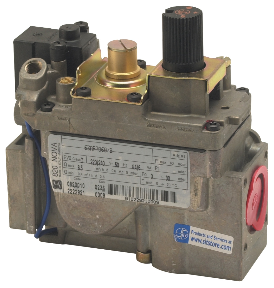
Solenoid valve coils develop resistance changes as they age. The SIT Sigma 0845063 gas block features two automatic solenoid valves that must be tested individually.
Coil resistance acceptance ranges:
- Measure coil resistance with power disconnected using an ohmmeter (usually the Rx100 scale)
- Record resistance values for both solenoids; typical range is 8-15 ohms for 230V coils
- Resistance values above 25 ohms indicate internal winding degradation and imminent failure
- Compare individual solenoid resistances; a difference greater than 30% between two identical coils suggests one coil is failing
- Resistance below 2 ohms indicates short circuit or contamination and requires immediate coil replacement
When testing the SIT Tandem gas block 0837013 with its dual solenoid configuration, match measurements against manufacturer data sheets. High resistance creates slow valve opening, delaying gas flow by 50-100 milliseconds—enough to cause ignition delays or flame detection faults.
Section 2: Response Time Testing Procedures
Measuring Solenoid Valve Opening and Closing Response
Response time testing reveals how quickly solenoid valves react to electrical signals. Slow response times are invisible to operators but directly affect ignition reliability.
Procedure for response time measurement:
- Connect an oscilloscope probe to the solenoid coil terminals (use 100:1 voltage probe for safety)
- Set oscilloscope to 100 microseconds per division time scale
- Apply 230V AC signal to the solenoid coil through a manual switch or function generator
- Capture the voltage waveform; measure time from signal application to coil current plateau (opening response)
- Record opening response time: acceptable range is typically 50-150 milliseconds for industrial solenoid valves
- Measure closing response time by capturing the voltage decay after signal removal; acceptable range is 30-80 milliseconds
- Repeat testing five times and record average values; consistency indicates stable operation
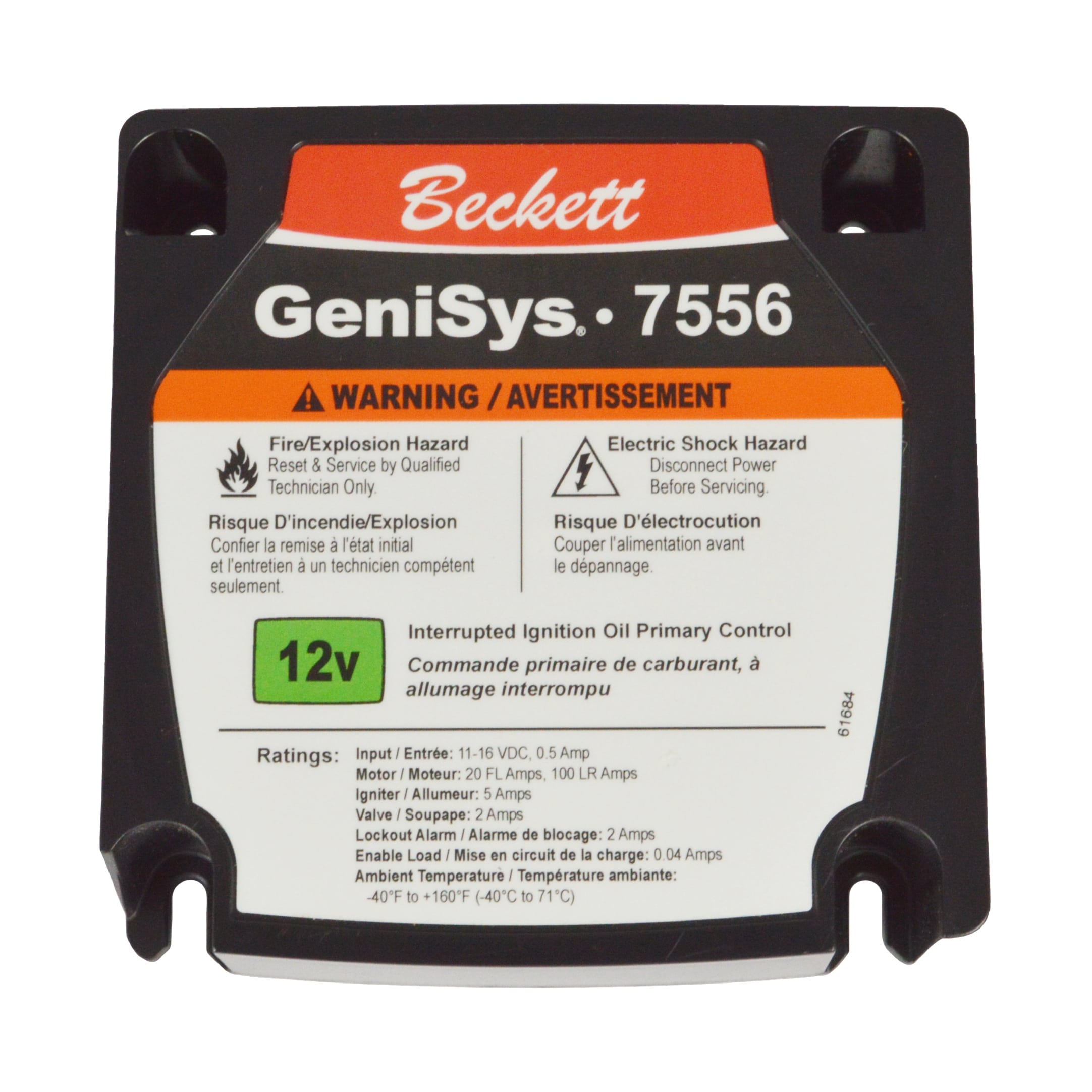
For the Beckett GeniSys® 7556 12V Oil Burner Control, response time testing becomes more critical because 12V circuits operate with lower signal margins. A 50-millisecond delay in flame detection response can cause the control to shut down a perfectly good flame.
Using Simulation and Bench Testing
Bench testing allows response time measurement without risking operational equipment. Create a test stand with:
- 230V AC or 12V DC power supply (appropriate to your control system)
- Function generator outputting square wave signals at 1-10 Hz
- Oscilloscope for waveform capture
- Load resistors simulating solenoid coil resistance (typically 10-20 ohms)
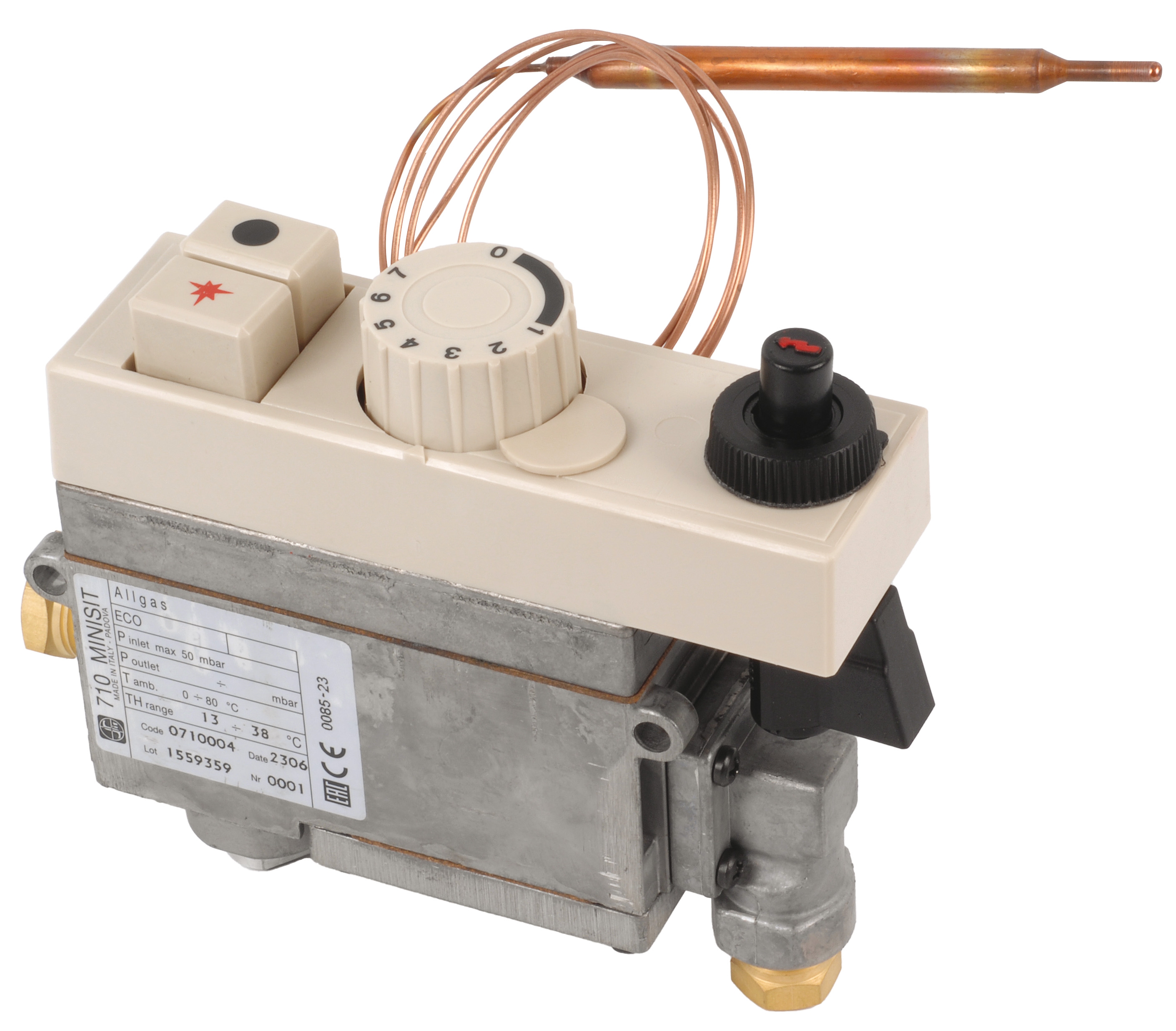
With the SIT Minisit 0710004 gas block removed from service, test response times on the bench before reinstalling. This isolates electrical faults from gas-side issues and prevents unnecessary field troubleshooting.
Bench test procedure:
1. Connect the control box to a stable AC/DC source matching field voltage
2. Apply test signals from the function generator at 2 Hz (0.5 second on, 0.5 second off)
3. Observe solenoid valve coil current through a 1-ohm sense resistor
4. Measure the time delay between signal input and coil current response
5. Repeat for 20 cycles and calculate average response time
6. Compare results against baseline data collected when the system was new
7. If response time has degraded by more than 25%, schedule component replacement
Section 3: Flame Detection Circuit Testing and Safety Interlocks
Verifying Flame Sensor Signal Strength
Flame detection failures often stem from weak input signals rather than faulty sensors. Most burner control systems require flame signals within specific voltage ranges.
Flame signal measurement procedure:
- Access the flame sensor circuit without removing the sensor from service
- Measure AC voltage across the flame sensor terminals using an AC voltmeter set to 2V scale
- Record baseline signal: typical range is 0.5-2.0V AC for thermocouple flame sensors
- Signal below 0.3V indicates carbon buildup on the sensor electrode or poor ground contact
- Signal above 3.0V suggests electrical noise interference or sensor electrode damage
- Test with the burner at idle and full fire to capture signal variation
- Document trend data weekly; declining signals over 2-3 weeks predict imminent flame detection failure
In industrial kitchens or damp environments common in Southeast Asia, salt spray and humidity corrode flame sensor electrodes rapidly. Monthly signal strength trending identifies degradation before complete failure occurs.
Safety Interlock Circuit Response
Safety interlocks protect equipment by preventing dangerous operation sequences. Test interlock circuits independently from the main control system.
Interlock testing sequence:
- Disable main burner ignition to prevent accidental firing
- Manually trigger interlock inputs (door switches, pressure switches, flow switches) one at a time
- Measure response time from interlock activation to control circuit lockout (typically <100 milliseconds)
- Verify that safety relay output de-energizes within 50 milliseconds
- Test all interlocks in combination to confirm they don't interfere with each other
- Document which interlocks produce fastest/slowest responses
- Replace or adjust any interlock exceeding 200 millisecond response time
The SIT 0577211 control box incorporates microprocessor-based safety logic requiring verification that electrical signals reach the processor within expected timeframes. Slow response times may cause the processor to ignore legitimate interlock signals, creating false safety faults.
Section 4: Troubleshooting Common Electrical Faults
Intermittent Flame Detection Faults
Intermittent faults—failures that appear and disappear unpredictably—indicate electrical noise or marginal signal margins rather than component failures.
Diagnostic approach:
- Connect an oscilloscope to the flame detection input while the burner operates
- Look for signal noise (AC ripple exceeding ±20% of baseline signal)
- Identify electrical interference sources: variable frequency drives, welding equipment, or radio transmitters within 10 meters
- Measure ground potential difference between the control box and flame sensor ground using a differential voltmeter
- Ground potential difference exceeding 50 mV indicates inadequate ground bonding
- Install shielded twisted-pair cabling with 360-degree shield connection at both ends to reduce noise
- Add ferrite clamps around solenoid coil leads to suppress switching noise
These interventions improve signal margin by 50-100%, eliminating intermittent faults without replacing components.
Solenoid Valve Chatter and Oscillation
Solenoid valves sometimes vibrate rapidly (chatter) instead of opening smoothly, creating erratic gas flow.
Chatter diagnosis and correction:
- Measure control signal frequency using an oscilloscope; chatter typically occurs at 100-300 Hz
- Check for resonance between the solenoid natural frequency and electrical supply frequency harmonics
- Measure solenoid coil inductance using an LCR meter; typical range is 0.5-2.0 henries
- Add a snubber diode (1N4007, 1A rated) across the solenoid coil if not already present—this eliminates voltage transients that cause chatter
- Install a 0.1 microfarad capacitor in parallel with the solenoid to filter high-frequency noise
- If chatter persists, the solenoid armature may have mechanical stiction; replace the valve
For systems using the SIT Tandem gas block 0837013, chatter in either solenoid should be addressed immediately because it causes pressure fluctuations that affect gas block output pressure regulation (±5 mbar).
Slow Burner Ignition or Delayed Flame Detection
When burners take 5-10 seconds to ignite after receiving a start signal, electrical delays in the ignition circuit are the usual cause.
Delay measurement and correction:
1. Measure time from burner start command to spark electrode voltage appearance using an oscilloscope
2. Normal ignition delay should be <500 milliseconds
3. Delays exceeding 1 second indicate slow response in the ignition transformer primary circuit
4. Check transformer primary winding resistance; values above 5 ohms suggest internal corrosion
5. Measure high-voltage output at the spark gap using a high-voltage probe; typical output is 6-8 kV for direct-spark ignition
6. Output below 4 kV causes inconsistent spark and ignition delays
7. Inspect the spark gap spacing (should be 2-4 mm for most burners) and clean electrode surfaces
8. Replace the ignition transformer if primary resistance is abnormal or secondary voltage is low
Best Practices for Electrical Maintenance Teams
Create a testing schedule:
- Monthly: Voltage supply checks and ground continuity testing
- Quarterly: Solenoid response time testing and flame signal verification
- Semi-annually: Complete circuit bench testing and interlock verification
- Annually: Transformer resistance testing and full control system commissioning
- Oscilloscopes must be calibrated annually
- Digital multimeters require bi-annual verification against known references
- Function generators should be checked monthly for signal accuracy
- Store baseline data from new installations for trending
- Record measurements on standardized forms
- Compare each measurement against prior readings to identify degradation trends
- Use trend analysis to predict failures 2-4 weeks before they occur
3G Electric has supported maintenance teams across Southeast Asia for over 35 years by providing quality control components and expert guidance. By implementing these electrical testing procedures, maintenance teams transform from reactive troubleshooting to predictive maintenance, reducing unplanned downtime by 40-60% while improving safety performance.