Understanding Controls & Safety Through Electrical Interlocking Architecture
Controls & Safety in modern industrial burner systems depend fundamentally on electrical interlocking—a failsafe architectural approach that prevents unsafe operational sequences by establishing logical dependencies between components. Unlike simple on/off controls, interlocking systems create mandatory sequencing rules: a burner cannot ignite unless the blower runs for a defined purge period, fuel solenoids remain closed until flame is confirmed, and all shutdown sequences must execute in proper order.
In Singapore's industrial landscape, where facilities operate under stringent standards and face tropical environmental challenges, electrical interlocking provides the critical safeguard against the most common causes of burner incidents: premature fuel introduction, unburned gas accumulation, and restart-without-purge scenarios. With over 35 years of experience distributing industrial equipment throughout Asia, 3G Electric has observed that the most reliable burner installations combine proven relay logic with redundant safety circuits.
The fundamental principle underlying electrical interlocking is the use of interlock switches and safety relays to enforce logical gates. Before a burner can energize its ignition circuit, multiple conditions must be simultaneously satisfied: the blower motor must run, demonstrating adequate combustion air availability; the fuel gas or oil must reach adequate pressure; and all shutdown interlocks from the previous cycle must have reset. Each condition is monitored by dedicated switches and validated through relay logic before permitting the next operational step.
Safety Relay Configuration and Dual-Channel Architecture
Modern Controls & Safety standards in Singapore increasingly mandate dual-channel safety relay systems, where two independent circuits monitor critical conditions and must both signal "safe" before the main burner circuit energizes. This redundancy architecture prevents single-component failures from creating dangerous conditions.
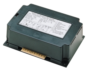
The Kromschroder Relay BCU 570WC1F1U0K1-E exemplifies this approach, providing a burner control relay that integrates multiple safety functions within a single module. This relay supports both direct ignition and pilot-based ignition modes, accommodating different burner designs while maintaining unified safety sequencing. The BCU 570 monitors flame presence through UV or ionization detection, enforces mandatory blower run-time before fuel introduction, and implements automatic shutdown if flame is lost during operation.
When selecting safety relays for Singapore installations, critical specifications include:
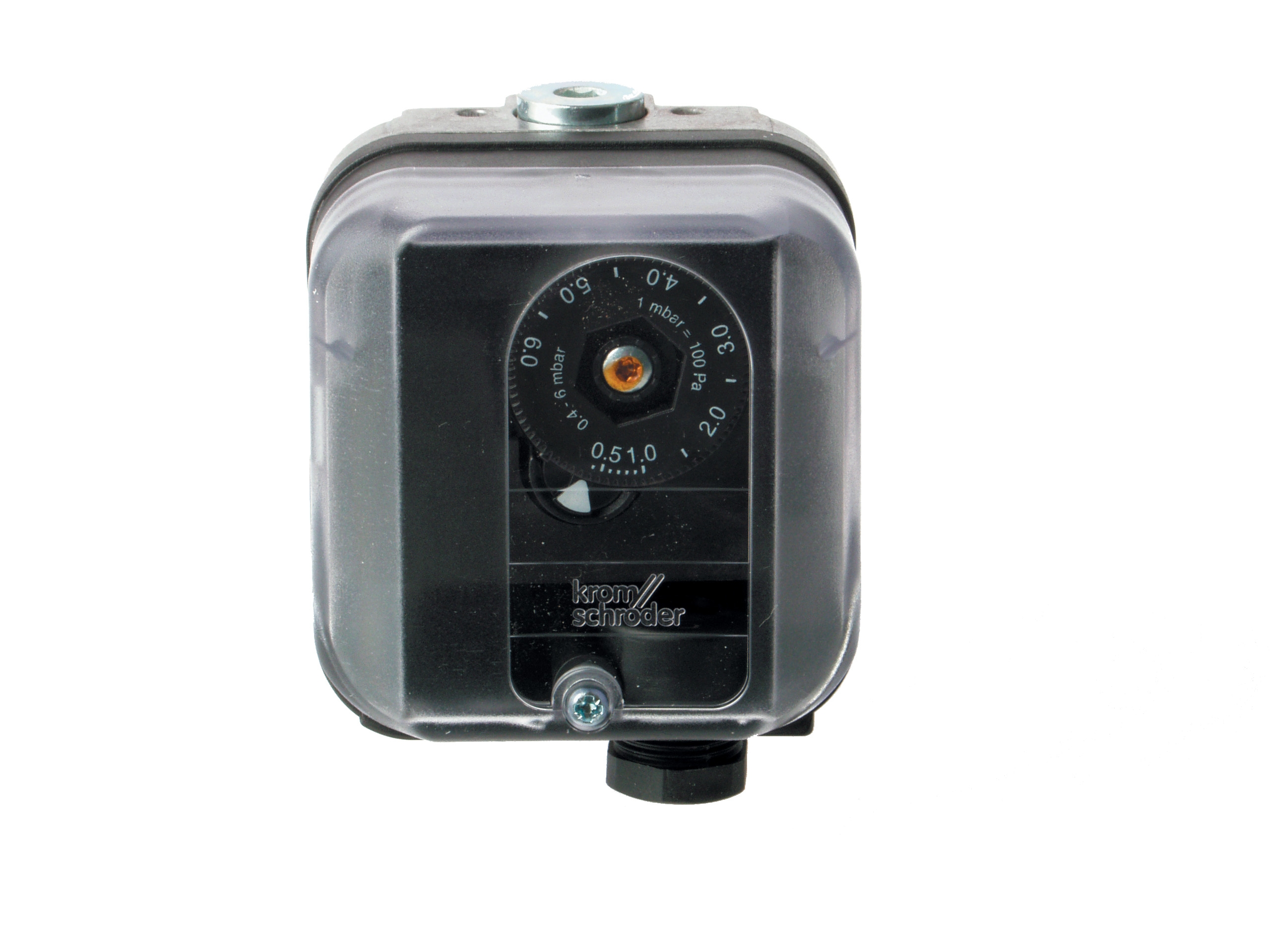
- SIL Rating (Safety Integrity Level): Singapore facilities increasingly require SIL 2 minimum for flame monitoring circuits. The Kromschroder Pressure switch DG 50U/6 achieves SIL 3 rating with Performance Level e, suitable for high-consequence applications where fuel line rupture could cause significant hazard.
- Response Time: Burner shutdown must occur within 1-4 seconds of flame loss, depending on fuel type and system design. Slow-acting relays create windows of unburned fuel accumulation. Most modern safety relays respond within 500-700ms.
- Electrical Supply Redundancy: Dual 24VDC supplies with automatic switchover prevent complete control loss during single-supply failure. Safety circuits should not depend on single power sources.
The Siemens Relay LFL 1.622 provides comprehensive control for medium to high-power burners, featuring integrated UV flame monitoring and ionization detection options. This dual-detection capability creates inherent redundancy: if UV sensing fails, ionization detection continues providing flame confirmation, and vice versa. The LFL 1.622 also controls air damper position for staged combustion, preventing excess fuel delivery during partial-load operation.
Pressure Monitoring Interlocks and Fuel Safety Sequencing
Pressure interlocks establish critical safeguards in fuel delivery systems. A burner cannot ignite if fuel pressure remains below minimum operating threshold, and ignition must cease immediately if pressure exceeds maximum safe limits. These conditions prevent fuel starvation (which causes ignition failure) and overpressure scenarios (which damage burners and create safety hazards).
In Singapore's industrial sector, gas-fired burners rely on proper pressure interlocking more than oil-fired systems, since gas accumulation creates explosion risk if released without ignition. The pressure switch must be SIL-rated, respond quickly to pressure changes, and provide direct electrical interlock signals—not merely alarm indications.
The Kromschroder DG 50U/6 pressure switch provides SIL 3-rated pressure monitoring across the full operating range of gas burners. Key operational characteristics include:
- Adjustable pressure setpoints: High and low switches with independent adjustment allow system designers to match specific burner requirements (typical ranges: 5-30 mbar for gas burners).
- Direct solenoid control: The switch output directly energizes or de-energizes fuel solenoids without intermediate logic—critical for ensuring fuel shutoff occurs even if control electronics fail.
- FM, UL, and GOST-TR certification: These certifications ensure the switch meets international safety standards and maintains compliance in cross-border operations common throughout Southeast Asia.
Pressure interlocking sequences typically follow this logic:
1. Blower energizes and runs for 10-30 second purge cycle
2. Ignition circuit energizes, attempting to establish flame
3. If ignition succeeds, fuel solenoid energizes (prevented by pressure interlock if fuel pressure is outside safe window)
4. Flame is confirmed within 2-4 seconds; if not detected, fuel solenoid closes and burner shuts down
5. During operation, pressure drops below minimum or exceeds maximum → immediate fuel shutoff and lockout
This sequencing prevents the catastrophic scenario of introducing unburned fuel into a combustion chamber without establishing ignition.
Gas Block Control Systems and Modulating Safety Architecture
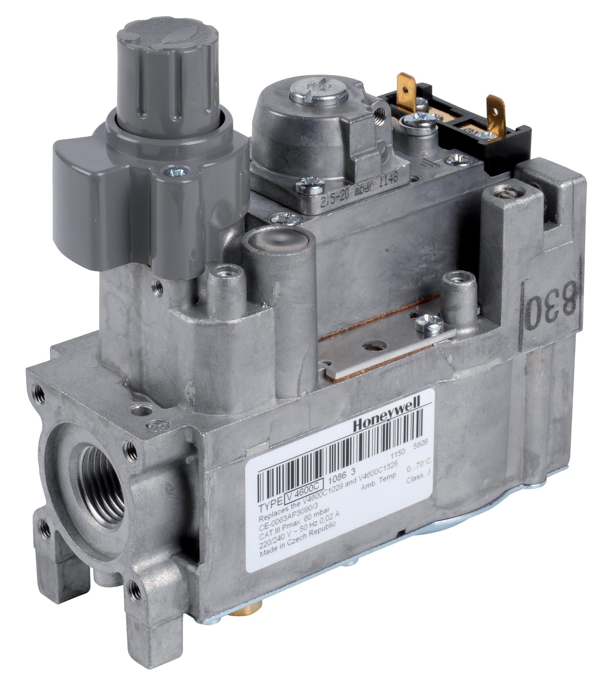
For more sophisticated burner installations requiring variable power output, modulating pressure regulators combine safety functions with load-responsive fuel delivery. The Honeywell Gas block VK 4105 C 1041 U provides electric modulation of gas pressure based on load demand signals, enabling burners to operate efficiently across 30-100% capacity while maintaining safety interlocks.
Modulating systems introduce additional complexity to Controls & Safety architecture: a burner must not only execute safe startup and shutdown sequences but also maintain safe conditions across variable operating points. This requires:
- Continuous pressure feedback monitoring: The gas block continuously measures outlet pressure and adjusts valve opening to maintain setpoint. If pressure drops unexpectedly (indicating line rupture or excessive consumption), the burner should reduce power or shut down.
- Electronic burner management coordination: Modern burner control units receive load demand from building management systems (BMS), relay these signals to the modulating gas block, and verify that actual fuel delivery matches expected levels through pressure sensing.
- Failsafe valve positioning: Should electric control power fail, the gas block must return to a safe state—typically fully closed or open to only pilot position, not random intermediate positions.
The Honeywell VK 4105 integrates M8×1 pilot connection and M5 pressure feedback threading, accepting modulation signals from relay units like the Siemens LFL 1.622. This integration creates a closed-loop safety system where fuel delivery is continuously validated against electrical command signals.
Ignition Circuit Isolation and Lockout Procedures
Ignition systems represent a concentrated energy source (typical output: 10-15kV with 5-20MJ energy) that must be absolutely inhibited during maintenance or troubleshooting. The Pactrol Housing P 16 DI CE provides the electrical isolation and energy storage for ignition circuits, operating at 230V supply with 12kV output and 10MJ stored energy.
Safety lockout procedures for ignition circuits must address several hazards:
- Stored energy in ignition transformer: Even after main power is disconnected, the high-voltage capacitor bank retains charge sufficient to cause electrical injury. Proper discharge procedures must be followed before technician contact with ignition components.
- Automatic restart circuits: Some burner controls include automatic restart after flame loss—a safety feature for normal operation but a significant hazard during maintenance if not properly disabled.
- Secondary ignition paths: Pilot ignition circuits often operate at lower voltage but still present electrical hazard. Lockout procedures must de-energize all ignition circuits simultaneously.
Best practice lockout sequences in Singapore industrial facilities:
1. Primary power isolation: Shut off main electrical supply to burner control panel and verify isolation with lockout/tagout (LOTO) devices
2. Secondary voltage verification: Test ignition circuit output with high-voltage probe to confirm discharge
3. Transformer discharge: For ignition systems with significant stored energy, connect discharge jumpers across high-voltage terminals for minimum 30 seconds
4. Flame sensing circuit isolation: Disconnect flame sensor wiring from control module to prevent accidental restart due to ambient light or electrical noise
5. Work authorization: Post work permits and ensure all personnel acknowledge lockout status before commencing work
Electrical interlocking systems must support these lockout procedures by providing maintenance switches that de-energize ignition circuits independently of normal operational controls. The Kromschroder BCU 570 and Siemens LFL 1.622 both feature maintenance selector positions that isolate ignition and solenoid circuits.
Practical Implementation: Burner Startup Sequencing in Singapore Industrial Facilities
A complete interlocking sequence for a commercial/industrial burner installation demonstrates how individual safety components integrate into unified safety architecture:
Pre-ignition Phase (30-45 seconds)
- Operator presses "Start" button, which energizes burner control relay
- Relay immediately energizes blower motor; fuel solenoid remains closed by pressure interlock or manual solenoid override
- Blower runs for mandatory purge period (typically 30 seconds for gas, 45 seconds for oil)
- Pressure switch confirms fuel supply is available but below solenoid threshold
- Once purge timer expires, ignition circuit energizes (either direct ignition for gas or pilot ignition for oil)
- Ignition transformer (like the Pactrol P 16 DI) develops high voltage across main or pilot burner
- UV or ionization flame detector monitors for flame establishment
- Within 2-4 seconds, flame must be detected by safety relay
- If detected, safety relay permits fuel solenoid to energize
- If not detected, relay automatically closes fuel solenoid and initiates lockout sequence
- Lockout requires manual reset or automatic reset after cool-down period
- Burner runs at full or modulated load depending on system configuration
- Pressure switch continuously monitors fuel supply (permitting shutdown if pressure becomes unsafe)
- Flame detector continuously monitors flame presence (causing shutdown if flame is lost)
- Load demand signal from BMS continuously adjusts modulating gas block for optimal efficiency
- Operator releases "Start" button or control system sends shutdown command
- Fuel solenoid immediately closes
- Burner burns remaining fuel in combustion chamber (coast-down period)
- After flame is no longer detected and mandatory cooling period expires, blower stops
- All safety interlocks reset, system ready for next startup cycle
This sequence prevents every major class of burner accident: unburned fuel accumulation, ignition without adequate air, flame loss during operation, and unsafe restart conditions.
Compliance and Performance Validation in Singapore
Singapore industrial facilities must comply with SS 638 (Code of Practice for the Use of Gas as Fuel in Appliances and Installations), which mandates specific interlock and safety relay requirements. Key regulatory expectations include:
- Dual-channel flame detection systems for SIL 2+ applications
- Mandatory blower run-time before fuel introduction
- Automatic shutdown within 4 seconds of flame loss
- Pressure interlocks preventing fuel delivery outside safe operating range
- Annual certification of burner and control system performance by qualified technicians
When procuring controls components, ensure suppliers provide documentation confirming:
- Certification to applicable international standards (EN 746-2, EN 676, EN 1854)
- Detailed functional specification sheets showing response times and electrical ratings
- Integration guidance for specific burner models and fuel types
- Maintenance and troubleshooting documentation suitable for local technicians
3G Electric maintains technical expertise with all major burner control manufacturers and can provide guidance on component selection, system integration, and compliance validation throughout Southeast Asia. Our 35+ years of industrial equipment distribution experience ensures access to tested, field-proven components rather than lowest-cost alternatives that may compromise safety or performance.