Understanding Controls & Safety Diagnostic Fundamentals
Industrial burner systems depend on interconnected Controls & Safety components that must function in precise sequence. When failures occur—whether slow ignition response, unexpected shutdowns, or nuisance lockouts—identifying the root cause quickly minimizes downtime and safety risk.
Diagnostic testing differs fundamentally from commissioning checks. During commissioning, you verify that new systems meet specifications. During diagnostics, you work backward from observed symptoms to identify which component in the control chain has failed or drifted out of specification.
3G Electric's 35+ years supplying industrial burner controls across Singapore and Southeast Asia has demonstrated that systematic diagnostic procedures save technicians countless hours compared to random component replacement. The difference lies in understanding the functional hierarchy: flame detection signals flow to control relays, which energize solenoid valves and ignition transformers through specific logic sequences. Testing must follow this signal path sequentially.
Section 1: Establishing a Diagnostic Testing Framework
Define the Symptom and Operating Context
Begin diagnostics by documenting exactly what the system does wrong and under what conditions. Is the ignition transformer not firing? Does the system lock out during normal operation? Does flame detection work intermittently? The symptom reveals which functional block to investigate first.
For example:
- No flame signal despite visible flame → Test flame detector and cable
- Solenoid valve won't open after ignition sequence → Test control relay output and solenoid coil
- Burner fires but system immediately shuts down → Test flame detection circuit stability
- Delayed ignition response → Test ignition transformer and control timing
Establish Safe Testing Conditions
Before connecting test equipment:
1. Isolate power supply at the main disconnect
2. Tag the breaker with maintenance in progress notice
3. Verify power is off using a digital multimeter set to AC voltage
4. Allow capacitors to discharge (wait 30 seconds minimum on systems with power supplies)
5. Review system documentation to understand voltage levels (110/120V or 220/240V) and control logic
6. Check for stored energy in pneumatic systems or hydraulic accumulators
Many industrial sites operate 24/7, making safe isolation critical. Never assume a control circuit is de-energized without verification.
Prepare Your Instrumentation
Minimum diagnostic tools for Controls & Safety testing:
- Digital Multimeter (CAT III 600V minimum rating)
- Clamp Meter (for measuring burner motor current)
- Insulation Tester (for detecting moisture in control components)
- Timing Light or Oscilloscope (for diagnosing ignition spark patterns)
- Pressure Gauge (for gas supply verification, 0–500 mbar range)
- Flashlight (for visual inspection of spark gaps and valve seating)
Calibrate your multimeter monthly using a known voltage source to ensure accuracy.
Section 2: Testing Control Relays and Logic Circuits
Visual and Mechanical Inspection
Before applying power, perform visual checks:
- Examine relay contacts for oxidation (black/green discoloration indicates corrosion)
- Check for loose terminal connections causing high resistance
- Inspect for moisture inside relay housings (sign of seal failure)
- Verify that relay mounting is secure and vibration-resistant
- Look for burn marks or discoloration on printed circuit boards
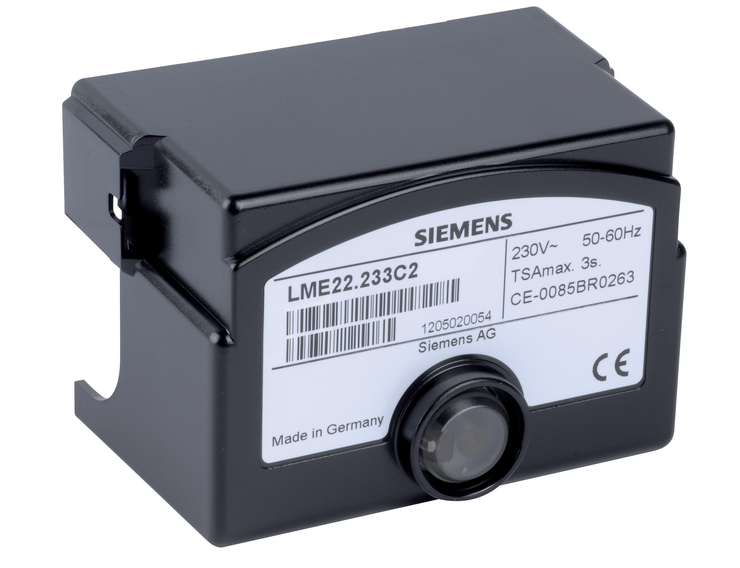
The Satronic Relay DMG 970-N MOD.01 and Siemens LME 22 233C2 relay are robust components, but environmental stress—heat, vibration, humidity in Southeast Asian industrial settings—can degrade performance over time.
Coil Voltage and Continuity Testing
With power safely isolated:
1. Measure coil resistance using your multimeter ohms setting
- Expected range: typically 100–500 Ω depending on relay type
- Resistance significantly higher suggests open circuit or partial break
- Zero resistance suggests short circuit
2. Test input signal continuity by disconnecting the control wire at the relay terminal
- Measure continuity from the control device (flame detector, pressure switch) to the relay input
- Resistance over 10 Ω indicates poor connections or corroded contacts
3. Verify output contacts mechanically by gently toggling the relay manual override lever (if equipped)
- You should hear a distinct click and feel positive engagement
- Sluggish response suggests a failing relay mechanism
Functional Testing Under Load
Once visual and resistance tests pass:
1. Restore power to the control circuit (not the main burner fuel supply yet)
2. Trigger the relay using the normal control input signal
3. Measure output voltage at the relay terminals—you should see supply voltage present
4. Monitor current draw using a clamp meter on the output circuit
- Solenoid valves typically draw 0.2–0.5 A
- Ignition transformers draw 1–3 A during spark generation
- Excessive current suggests a short circuit; no current suggests open circuit
5. Listen for audible clicking when the relay energizes and de-energizes
- Missing click indicates mechanical failure
For systems using the Sit Control box Sit 0579311, perform the full functional sequence: manual reset, ignition timing verification, and flame signal acquisition.
Addressing Intermittent Relay Failures
Intermittent failures—where the relay works sometimes—are notoriously difficult to diagnose because symptoms may not appear during testing. Follow these procedures:
1. Document failure frequency over several days
- Record time of day, ambient temperature, and recent maintenance
- Correlate with humid weather or after extended shutdown periods
2. Check for thermal cycling effects
- Measure coil resistance when cold and again after 2 hours of operation
- Change over 5% indicates thermal drift
3. Perform insulation testing on all control wiring
- Use a megohm meter set to 500V DC
- Insulation resistance should exceed 1 MΩ
- Values between 0.1–1 MΩ indicate moisture contamination
- Below 0.1 MΩ means immediate wire replacement is needed
Section 3: Diagnosing Flame Detection Circuits
Understanding Flame Signal Pathways
Flame detection is the critical safety element in all modern burner controls. The flame detector (whether UV or infrared) must continuously confirm that fuel is burning. Any interruption in this signal causes the control relay to cut fuel supply within milliseconds.
Common flame detection problems:
- False signals (system sees flame when there isn't any)
- Signal loss during normal burning (intermittent flame signal)
- Delayed signal acquisition (system waits 10+ seconds after ignition)
- Failure to signal flame absence (doesn't cut fuel when flame goes out)
Testing Infrared Flame Detectors
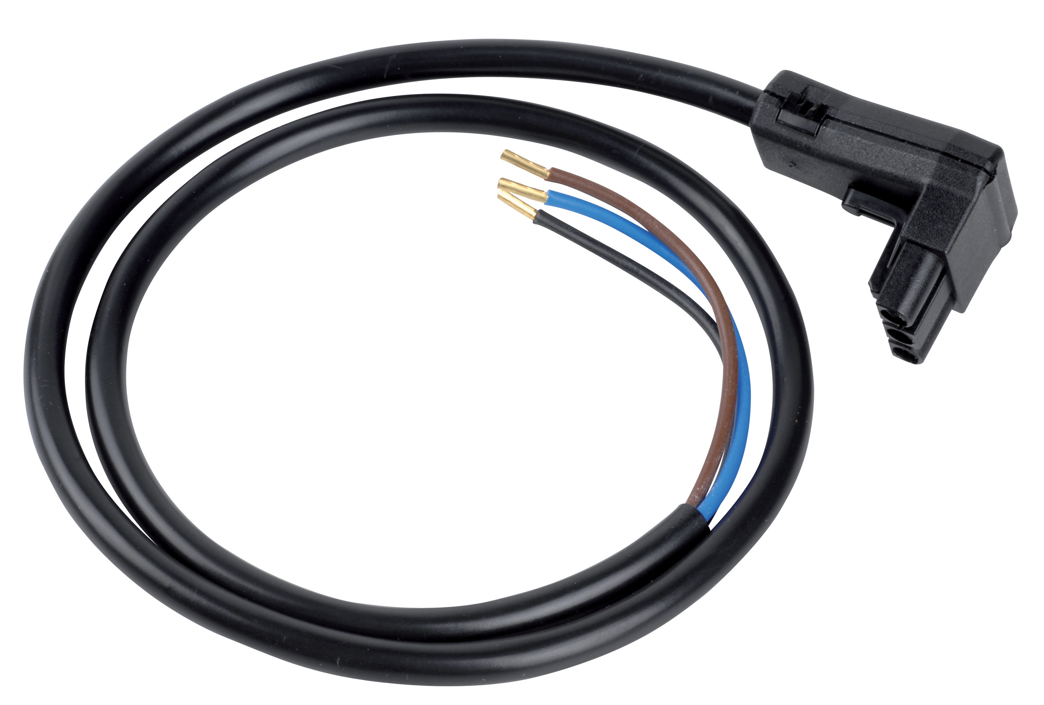
Infrared detectors like those used with the Satronic Cable for cell IRD10... sense radiation in the 800–1100 nm spectral range, with peak sensitivity at 950 nm.
Cable and connector inspection:
1. Visually trace the cable from the detector to the control relay
2. Check for:
- Pinches or abrasions in the insulation
- Loose connector pins (gently tug; pins shouldn't move)
- Corrosion on connector contacts (clean with isopropyl alcohol and cotton swabs if found)
- Cable routing near high-temperature surfaces (should be 100 mm minimum clearance)
3. Measure cable resistance:
- Each conductor should measure less than 1 Ω
- Resistance over 5 Ω indicates connection problems
Detector lens and optical path:
1. Examine the detector window for dust, soot buildup, or condensation
- Silicon or borosilicate windows can become opaque if not maintained
- Clean with soft lens cloth and isopropyl alcohol if necessary
2. Verify unobstructed line of sight to the flame
- Position a mirror or reflective surface at the flame location
- Observe if the detector lens glints (indicates direct sight line)
- Any obstruction (baffle plates, tube discoloration) blocks the signal
3. Test detector sensitivity using a test lamp
- Some detectors have built-in test ports; check the technical data
- Hold an infrared test lamp 30 cm from the detector
- Measure signal output using your multimeter (typically 5–10 VDC for strong signal)
- If signal is weak or absent, the detector requires replacement
Signal stability during operation:
1. During a normal burner ignition sequence, monitor the flame signal voltage continuously
- Connect your multimeter to the detector output (do not disconnect the circuit)
- Use the multimeter's data-logging feature if available
- Watch for fluctuations or dropouts
- Occasional 0.5 V variations are normal; swings exceeding 2 V indicate optical or electrical problems
2. After stable flame establishment, gradually increase burner load
- Flame signal should remain stable within 10% variation
- If signal weakens dramatically at high fire, combustion quality or detector positioning may be incorrect
Testing Solenoid Valve Response in the Signal Chain
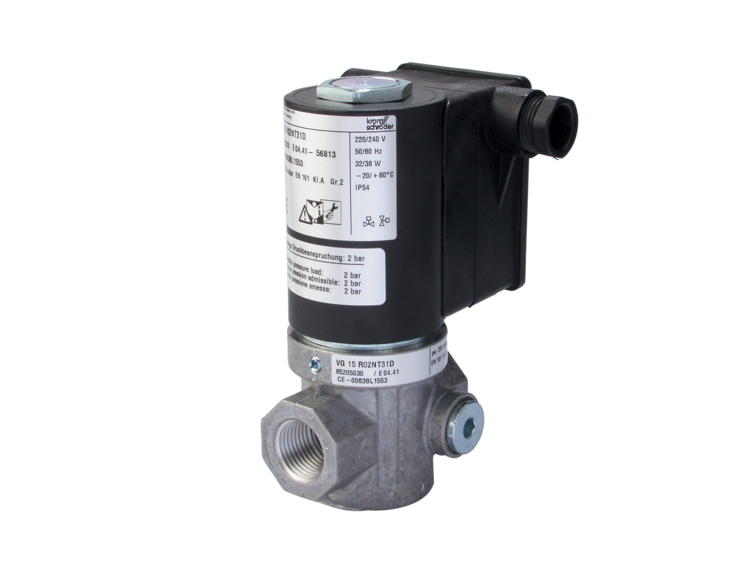
The Kromschroder Fast gas solenoid valve VAS 115R/NQ must respond within 100 milliseconds when the control relay energizes it. Slow solenoid response can cause:
- Delayed ignition (delayed fuel delivery)
- Unburned gas accumulation (explosion risk)
- Control system lockout (safety shutdown)
1. Measure coil resistance (power off):
- Fast-response solenoids typically measure 10–30 Ω
- Values outside this range indicate coil problems
- Infinite resistance means open circuit; zero resistance means short circuit
2. Test coil insulation with a 500V megohm meter:
- Acceptable resistance: 10 MΩ minimum
- Below 1 MΩ indicates moisture inside the solenoid coil
- Corroded springs and plungers frequently cause low insulation readings
3. Verify supply voltage to the solenoid:
- With power on and control relay energized, measure voltage at solenoid terminals
- Should match system supply voltage (typically 110/120V or 220/240V)
- If voltage is present but solenoid doesn't click, the coil is open
- If voltage is absent, the control relay output has failed
Mechanical response timing:
1. With gas supply isolated at the main block valve:
- Connect a low-pressure gauge (0–500 mbar) downstream of the solenoid
- Energize the solenoid from the control relay
- Observe the pressure gauge needle—it should rise smoothly within 150 ms
2. Listen for the solenoid plunger click:
- Fast solenoids produce a sharp, immediate click
- Sluggish solenoids produce a delayed or muffled click
- No click with power present indicates mechanical jamming or coil failure
3. Check for gas leakage at the solenoid seat:
- Apply soapy water to the solenoid outlet while it's de-energized
- Any bubbles indicate internal seat leakage
- Leaking solenoids must be replaced (they cannot be reliably repaired)
Section 4: Systematic Troubleshooting Workflow and Documentation
Creating a Diagnostic Decision Tree
Linear testing (testing component A, then B, then C) is inefficient. Instead, use a decision tree based on observed symptoms:
If burner won't ignite:
- Test 1: Measure voltage to ignition transformer → No voltage?
- Test 2b: Check input signal from pressure switch → No signal? Verify switch adjustment
- Test 1 continued: Voltage present at transformer?
- Test 4a: Check transformer insulation resistance → Breakdown? Replace transformer
- Test 4b: Verify spark gap setting (typically 2–4 mm) → Adjust or clean
If system locks out after ignition:
- Test 1: Measure flame detector signal during stable flame → Weak or absent?
- Test 2b: Check cable continuity and insulation → Damaged? Replace cable
- Test 2c: Test detector with test lamp → No response? Replace detector
- Test 1 continued: Flame signal present?
- Test 4: Verify relay coil receives input signal → Relay is responding correctly; investigate flame signal stability
Documenting Results for Future Reference
Proper documentation transforms individual diagnostics into institutional knowledge:
Create a diagnostic log entry containing:
1. System identification: Burner model, control relay type, flame detector model, solenoid valve model
2. Problem description: Exact symptoms, frequency, and operating conditions when failure occurs
3. Initial observations: Visual inspection findings, unusual odors, noises, or signs of overheating
4. Test sequence performed: Each test number, what you measured, and the measured value
5. Root cause identified: The specific component that failed or specification that was out of range
6. Corrective action taken: Replaced component SKU, adjusted setting, cleaned part, etc.
7. Post-repair verification: Tests performed to confirm the problem is solved
8. Time spent: Hours from problem identification to return to normal operation
Over time, these logs reveal patterns—such as a particular batch of relays failing prematurely, or flame detection problems correlating with seasonal humidity changes. This intelligence allows you to implement preventive measures.
Building Long-Term System Reliability
After solving an immediate problem, take these additional steps:
1. Schedule preventive maintenance based on failure mode
- If lens cleaning solved the problem: clean every 6 months
- If corroded contacts caused signal loss: inspect connections quarterly
- If thermal cycling caused intermittent failure: improve ambient temperature control
2. Stock spare components that have proven problematic
- Keep one extra control relay, solenoid valve, and flame detector on hand
- When a failure occurs, you can replace and repair, rather than waiting for parts
- 3G Electric maintains inventory of all listed components for rapid availability
3. Train operators to recognize early warning signs
- Longer-than-normal ignition delays may indicate solenoid response degradation
- Repetitive lockouts may signal flame signal instability before complete failure
- Burning smell may indicate electrical overheating in relay or transformer
4. Update system documentation with findings
- Mark which components are aged and approaching end-of-life
- Note any modifications or workarounds implemented
- Record calibration settings for all adjustable devices
Singapore's demanding industrial environment—with high humidity, temperature extremes, and intensive operating schedules—requires rigorous Controls & Safety maintenance. Systematic diagnostics, proper documentation, and planned component management reduce emergency failures by an estimated 60–70% based on 3G Electric's experience with hundreds of local facilities.