Understanding Burners & Combustion Diagnostics in Singapore's Industrial Environment
Burners & Combustion systems in Singapore's high-humidity, tropical climate face unique operational challenges. Equipment operates continuously under demanding conditions, making reliable diagnostics essential for minimizing downtime and ensuring safety compliance. Over 35 years, 3G Electric has supported HVAC contractors across Southeast Asia in developing systematic troubleshooting protocols that reduce diagnostic time and improve first-contact resolution rates.
Effective combustion diagnostics combines field observation, instrumentation, and systematic testing. When a burner system fails or underperforms, contractors must quickly distinguish between combustion problems, control system failures, and fuel delivery issues. This guide walks you through practical diagnostic procedures using standard tools available on most service vehicles.
Section 1: Initial Assessment and Safety Verification Protocols
Pre-Diagnostic Safety Checklist
Before performing any combustion diagnostics, establish safe working conditions:
- Verify the burner is completely shut down and locked out per PSM (Process Safety Management) requirements
- Check for residual pressure in fuel lines using a calibrated manometer
- Confirm adequate ventilation and test atmosphere for explosive gas concentrations
- Inspect visible flame pathways and combustion chamber for carbon deposits or structural damage
- Verify electrical isolation and confirm no stored energy in control circuits
Systematic visual inspection often reveals the root cause without instrumentation:
- Flame appearance: Color, stability, and size indicate combustion quality. Yellow/orange flame suggests incomplete combustion; blue indicates proper mixing. Flickering or lifting flame signals air-fuel ratio problems.
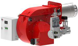
- Fuel nozzle condition: Blockages, erosion, or misalignment prevent proper atomization. On dual-fuel burners like the FBR KN 350/M, check both gas and oil nozzles for debris.
- Combustion chamber deposits: Heavy carbon buildup indicates rich running or inadequate air supply. Light deposits suggest normal operation; black soot indicates incomplete combustion.
- Air register position: Incorrect damper settings restrict combustion air flow. Compare actual position to design specifications.
- Electrode condition: On ignition-equipped burners, check electrode gaps (typically 3-4mm) and inspect insulators for cracking or carbon tracking.
Establish baseline pressures to isolate system faults:
1. Connect calibrated manometer to fuel supply inlet
2. Record supply pressure during startup and steady-state operation
3. Note any pressure fluctuations exceeding ±5% during modulation
4. Compare against manufacturer specifications (typically 2-4 bar for gas burners)
5. Test combustion air pressure using pitot tube if blower performance is questioned
Section 2: Combustion Analysis and Air-Fuel Ratio Diagnostics
Portable Combustion Analyzer Operation
Modern contractors should maintain a portable combustion analyzer as a core diagnostic tool. This instrument measures exhaust gas composition to determine:
- Oxygen (O₂) content: Indicates excess air. Target 3-4% O₂ for natural gas, 2-3% for oil burners
- Carbon dioxide (CO₂) content: High CO₂ (8-10%) suggests complete combustion; low values indicate excess air
- Carbon monoxide (CO) content: Any CO above 100 ppm indicates incomplete combustion; values >400 ppm demand immediate correction
- Stack temperature: Baseline 150-200°C; excessive temperatures suggest combustion problems
- Efficiency calculation: Modern analyzers calculate combustion efficiency directly
1. Allow burner to run 10 minutes for thermal stabilization
2. Insert analyzer probe into flue gas stream at 6-inch depth, away from turbulent zones
3. Record O₂, CO, CO₂, stack temperature, and efficiency readings
4. Test at minimum fire (low modulation) and high fire positions
5. Document all readings with timestamp and ambient temperature
6. Compare results against design envelope from manufacturer data sheet
Interpreting Results for Common Issues
- High O₂ + low flame intensity: Combustion air damper set too open; adjust register downward
- High CO + sooty flame: Air supply insufficient; check for blockages in air intake or filter clogging
- Unstable readings + fluctuating flame: Gas pressure regulator may be failing; verify with secondary manometer
- Consistently low efficiency: Nozzle wear or fuel atomization degradation; consider replacement using matched OEM components
For high-capacity applications using FBR HI-GAS P1500/M, oxygen content typically targets 2.5-3.0% due to dual-stage modulation design. Verify load-dependent combustion curves match factory settings.
Section 3: Control System and Ignition Circuit Diagnostics
Flame Detection Circuit Testing
Most modern burners employ UV or infrared flame detection. When flame-related faults occur:
1. Measure detector output signal using a digital multimeter on mV DC scale (typically 0-10V DC)
2. During flame-on state, signal should exceed 5V; during flame-out, signal drops below 1V
3. Response time should occur within 1-2 seconds of ignition
4. If signal remains static or responds slowly, clean detector window (mineral deposits accumulate in humid Singapore climate)
5. Verify detector positioning—angular misalignment >15° causes detection failure
Fuel Valve and Solenoid Testing
Electrical fuel valves represent critical failure points:
- Coil continuity: Measure resistance (typically 30-90 ohms for 230V solenoids). Infinite reading indicates failed coil
- Energization voltage: Confirm supply voltage matches nameplate rating ±10%
- Mechanical response: Listen for audible click when energized; absence suggests stuck plunger
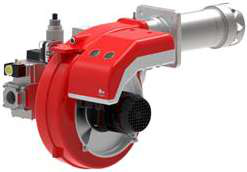
- Pilot gas flow: On two-stage burners like FBR GAS X3/2 CE-LX4, verify pilot solenoid opens first, enabling main valve opening
- Valve seal integrity: After shutdown, monitor fuel pressure drop over 60 seconds; pressure holding indicates good seal
For burners with proportional control:
1. Access control module and verify PID tuning parameters match equipment specifications
2. Observe response to load changes—smooth modulation without hunting indicates proper tuning
3. Test potentiometer linearity by manually adjusting and recording output across full range
4. Verify load cell or pressure transducer signal transmission to control module
5. Check for parameter drift by comparing current values to documented baseline settings
On commercial systems, excessive hunting (oscillating between high and low fire) requires PID gain adjustment—reduce proportional gain by 10-15% increments until stable.
Section 4: Performance Verification and System Optimization
Thermal Load Testing
After diagnostics and corrections, verify system performance under load:
1. Bring system to operating temperature and stabilize for 15 minutes
2. Measure heat output using BTU calculation: (Flow rate in GPM) × (Temperature rise in °F) × 500
3. Compare against design specification (nameplate typically shows kW or BTU/h)
4. For gas burners, verify modulation response under variable demand
5. Record all results for service history documentation
For applications using FBR HI-GAS P550/M CE TL or FBR HI-GAS P650/M CE TL, large-scale burners require verification of both low-fire (minimum stable output) and high-fire performance throughout the design operating range.
Commissioning Documentation
Complete troubleshooting requires proper documentation:
- Record baseline combustion analysis before and after service
- Document all component replacements with part numbers and serial data
- Create troubleshooting flowchart specific to each installation for future reference
- Photograph flame appearance under normal operation for visual comparison
- Establish preventive maintenance intervals based on findings (typically 6-12 months for high-use Singapore installations)
Tropical humidity and salt spray environments accelerate component degradation:
- Increase detector cleaning frequency to monthly (vs. quarterly in temperate climates)
- Verify air intake filters monthly; clogging occurs 2-3× faster than standard rates
- Apply corrosion inhibitor to exposed electrical connections annually
- Check control module condensation annually—install desiccant packs if moisture detected
Practical Field Toolkit for Burner Diagnostics
Maintain these instruments on your service vehicle:
- Calibrated digital manometer (0-20 bar range)
- Portable combustion analyzer (O₂, CO, CO₂, temperature)
- Digital multimeter with mV DC capability
- Fuel pressure test gauge
- Combustion air pitot tube
- Electrode gap measuring tool
- Nozzle cleaning kit with replacement gaskets
- Thermal imaging camera (identifies hot spots indicating combustion problems)
Conclusion
Burners & Combustion diagnostics combines systematic observation with precise instrumentation. By following these step-by-step protocols, HVAC contractors in Singapore can rapidly identify root causes, execute targeted repairs, and verify system restoration. 3G Electric's 35+ years supporting Southeast Asian contractors ensures access to genuine replacement components and technical specifications for all burner types, from compact two-stage units like the FBR GAS X3/2 CE-LX4 to large industrial systems. Contact our technical team for specific diagnostic guidance on your installed equipment.