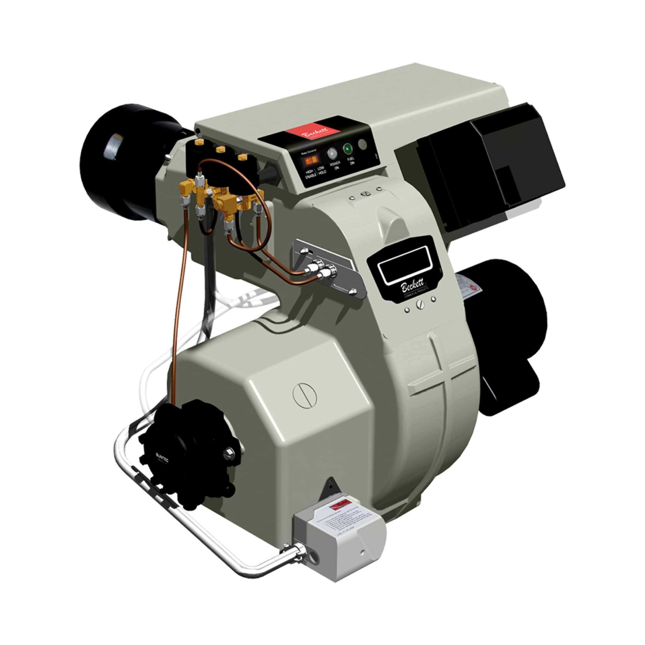
Understanding Burners & Combustion Solenoid Valve Response Timing
Burners & Combustion systems depend critically on precise solenoid valve timing to regulate gas flow during ignition, modulation, and shutdown sequences. As a procurement engineer, understanding how response delays affect system performance is essential for specifying the right components and diagnosing field problems.
Solenoid valve response time—the interval between electrical signal and actual gas flow initiation—typically ranges from 50-300 milliseconds depending on valve design, pressure conditions, and coil energization. Delays exceeding manufacturer specifications create combustion instability, failed ignitions, and potential safety hazards. With 35+ years of experience distributing industrial combustion equipment globally, 3G Electric has observed that timing issues account for approximately 25-30% of burner control failures, yet remain frequently overlooked during initial troubleshooting.
The distinction between slow-acting and fast-acting solenoid valves becomes critical in different combustion scenarios. Slow-response valves (typically 150-250ms) manage main gas feed with gentle pressure ramp-up, preventing pressure spikes that damage downstream equipment. Fast-response valves (typically 50-100ms) control pilot gas, enabling rapid ignition and flame stabilization. Specifying incorrect valve types—or using degraded valves with compromised response characteristics—creates mismatches that cascade through the entire combustion control sequence.
Diagnosing Solenoid Valve Response Delays and Timing Issues
Symptoms of Degraded Response Performance
Procurement engineers should recognize these operational indicators suggesting solenoid valve timing problems:
- Delayed ignition or intermittent pilot flame: Ignition attempts fail despite correct fuel supply and spark/ignition source present. The delay between ignition command and flame establishment exceeds 3-5 seconds.
- Slow fuel ramp-up: Main burner fuel pressure rises gradually rather than reaching set-point within 1-2 seconds, creating weak initial combustion and incomplete fuel atomization.
- Uncontrolled pressure spikes during shutdown: When burners shut down, fuel pressure surges briefly before solenoid blocks flow, indicating slow closing response or internal leakage during deactivation.
- Hunting or unstable modulation: Burner modulation oscillates between high and low output rather than smoothly tracking load demands, suggesting timing mismatch between fuel valve and air control systems.
- Flame safeguard nuisance shutdowns: Flame detection circuits register flame loss during normal operation because slow valve response creates momentary flame dips during modulation transitions.
Step-by-Step Diagnostic Approach
1. Verify Electrical Signal Integrity
Before assuming solenoid valve failure, confirm that control circuits deliver proper voltage and pulse timing:
- Measure voltage at solenoid coil terminals using a multimeter during operation. Standard industrial solenoids expect 24VDC or 120VAC; voltage below 90% of rated value delays or prevents actuation.
- Use an oscilloscope to observe signal waveform, confirming clean rising and falling edges without noise or distortion that could delay coil energization.
- Check relay contact condition if an external relay drives the solenoid. Corroded relay contacts introduce 10-50ms delays before current reaches the solenoid coil.
Internal solenoid degradation manifests as:
- Measure coil resistance with a digital multimeter. Compare against nameplate specifications; resistance increase of 15-20% indicates coil insulation breakdown and reduced electromagnetic force.
- Inspect solenoid plunger travel by carefully removing the solenoid assembly (with system depressurized and isolated). Plunger should move freely with minimal friction; carbon buildup or corrosion on the plunger rod creates mechanical resistance.
- Listen for audible clicking when energizing the solenoid. Absence of clicking suggests insufficient electromagnetic force to overcome spring pressure or seal friction.
For critical applications, directly measure solenoid response using:
- Pressure transducers: Install a transducer upstream of the solenoid valve with data logging capability. Energize the solenoid and record the time interval from energization to pressure change. Industry standard expects main gas valves to respond within 200ms and pilot valves within 100ms.
- Flow meters: In pilot circuits, measure gas flow initiation time using thermal or mechanical flow indicators.
- Visual inspection with pressure gauges: In field conditions, observe gauge needle movement while an assistant activates the solenoid switch. Timing delays become evident as noticeable lag between switch activation and gauge response.
Solenoid response degrades significantly at pressure extremes:
- At inlet pressures below 0.5 bar (7 psi), pilot solenoid response may exceed acceptable limits because differential pressure across the solenoid is insufficient to overcome spring and seal friction.
- At pressures exceeding rated maximum (typically 20-25 bar for standard industrial valves), response time increases due to higher pressures resisting plunger movement.
- For systems with variable inlet pressure (common in modulating burners), specify valves with flat response curves across the expected operating range.
Component Selection and Timing Optimization
Matching Valve Response Characteristics to Burner Type
Procurement engineers must align solenoid valve specifications with specific combustion application requirements:
For Pilot Gas Control (Ignition and Flame Stabilization)
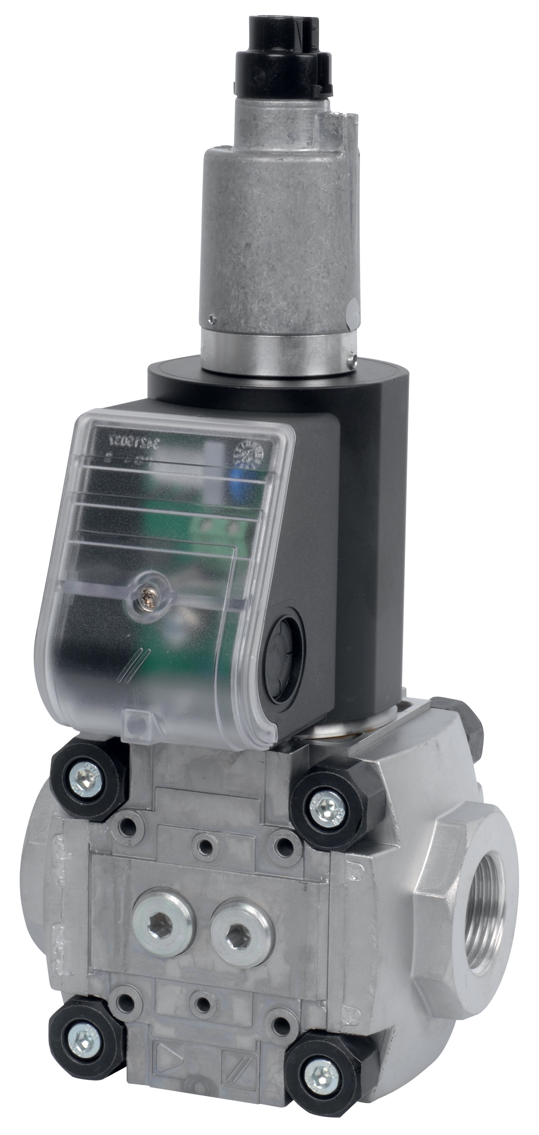
Use fast-response solenoid valves such as CBM Fast gas solenoid valve VAS 110R/NW and CBM Fast gas EV VAS 365R/NW. These valves energize quickly to establish pilot flame within 1-2 seconds, critical for successful ignition sequences and flame safeguard compliance. Fast-response design minimizes the window during which flame loss can occur before the main burner ignites.
For Main Fuel Gas Supply (Combustion Modulation)
Specify slow-response valves like CBM Slow gas solenoid valve VAS 340R/LW and CBM Slow gas solenoid VAS 125R/LW. These valves provide controlled fuel ramp-up over 150-250 milliseconds, preventing pressure shock waves that damage fuel nozzles, atomizers, and downstream control components. The controlled opening also allows combustion air systems to establish proper air-fuel ratios before fuel reaches peak flow.
Relay Timing Coordination
Control relays introduce additional timing delays. The CBM Relay DMG 970-N MOD.03 provides relay contact sequencing that ensures pilot solenoid energization precedes main gas solenoid by 100-200ms, a critical timing requirement. During procurement specification, confirm that relay contact closure time—typically 10-20ms—remains consistent across the expected relay life. Relays with degraded contact surfaces may exhibit 30-50ms delays, accumulating into unacceptable total system response times.
System Integration and Response Timing
When procuring replacement solenoid valves, document the complete timing sequence:
- Pilot ignition command to pilot flame establishment: typical maximum 3 seconds
- Pilot flame confirmation to main gas valve energization: 0.5-1 second delay (safety interlock requirement)
- Main gas valve energization to full fuel flow: 200-300ms for slow-response valves
- Combustion stabilization to load modulation availability: 2-5 seconds
Specifying valves independently without considering total system response creates timing mismatches. A new fast-response main gas valve installed in a system designed for slow-response characteristics may cause pressure oscillations and flame instability.
Maintenance and Preventive Actions for Solenoid Reliability
Scheduled Inspection Protocols
Establish maintenance intervals aligned with burner duty cycles:
- Monthly: Visually inspect solenoid coils for water accumulation, corrosion, or physical damage. Ensure electrical connectors remain clean and fully seated.
- Quarterly: Measure solenoid coil resistance and compare against baseline readings established during installation. Trending coil resistance predicts failure 2-4 weeks in advance as insulation degrades progressively.
- Annually: Perform complete response time verification using pressure measurement techniques described above. Document results to establish trending data.
- After any flame safeguard shutdown: Inspect solenoid valves and coils immediately, as nuisance shutdowns often precede catastrophic valve failure by hours or days.
Environmental Protection Measures
Solenoid valve longevity depends significantly on environmental conditions:
- Install solenoid valve protective covers in industrial environments with dust, moisture, or corrosive gases that degrade coil insulation.
- Ensure adequate ventilation around solenoid coils to prevent heat accumulation, which accelerates insulation breakdown. Coils should remain below 80°C under normal operating conditions.
- Apply dielectric grease to electrical connectors in high-humidity applications to prevent corrosion and contact resistance increase.
- Route fuel supply lines away from direct contact with hot burner components (above 60°C) that could degrade solenoid valve seals and coil insulation.
Upstream System Maintenance
Solenoid valve response performance depends on clean fuel supply:
- Verify fuel supply filter condition monthly. Clogged filters reduce inlet pressure, degrading solenoid response and increasing coil current draw that leads to premature failure.
- Install pressure regulators upstream of solenoid valves to maintain consistent inlet pressure within the narrow operating window specified by the valve manufacturer.
- Drain moisture and contaminants from fuel supply tanks quarterly. Water in gas supply causes corrosion inside solenoid valve bodies, creating friction that slows plunger movement.
Troubleshooting Decision Tree for Rapid Problem Resolution
Symptom: Delayed ignition or pilot flame establishment
Proceed through this sequence: Verify 24VDC supply at solenoid terminals (minimum 21.6V required) → Measure solenoid coil resistance and compare to nameplate (should be within ±10%) → Test fast-response pilot solenoid with bench pressure test (energize at 1 bar supply, should achieve flow within 100ms) → If solenoid fails bench test, replace with equivalent fast-response valve specification → If solenoid passes but system still fails, check relay contact timing and fuel supply pressure downstream of filters.
Symptom: Slow fuel ramp-up during main burner startup
Confirm inlet pressure meets minimum requirement (typically 2-3 bar for main gas systems) → Measure actual solenoid response time using pressure transducer (should be 200-250ms maximum for slow-response valves) → Inspect fuel filter for clogging (pressure differential exceeding 0.5 bar indicates restricted flow) → Verify solenoid outlet pressure relief valve operation (relief should not open until 2-3 bar above set pressure) → If pressure relief opens prematurely, replace or recalibrate before replacing main solenoid valve.
Symptom: Uncontrolled fuel pressure spikes during shutdown
Measure solenoid closing time using pressure transducer (should reach near-zero flow within 150ms after de-energization) → Listen for solenoid clicking during deactivation (absence suggests mechanical stiction) → Install pilot-operated check valve downstream of solenoid if not already present (prevents backflow that creates pressure spikes) → If closing time exceeds 200ms, solenoid plunger stiction or seal wear requires replacement → Verify fuel supply contains no water (causes corrosion and increased friction) by draining supply tank and inspecting for discoloration.
Procurement Recommendations and Supplier Considerations
When evaluating solenoid valve suppliers for your organization's global operations, 3G Electric's 35+ years of experience maintaining critical combustion systems informs these procurement criteria:
1. Response time verification: Insist on independent third-party response time testing data, not just manufacturer claims. Compare actual field performance across multiple installations.
2. Spare parts availability: Specify valve models with established supply chains in all regions where your burner systems operate. Single-source components with extended lead times create extended downtime during failures.
3. Cross-reference compatibility: Document exact valve model compatibility with your control relays and flame safeguard circuits. Generic "24VDC solenoid valves" from unfamiliar manufacturers may have different response characteristics that destabilize existing systems.
4. Temperature and pressure rating margins: Select valves rated 20-30% above maximum expected operating conditions. This provides reliability margin for pressure transients and thermal stress from repeated startup cycles.
5. Coil redundancy options: For critical applications where burner shutdown creates safety or economic risk, consider dual-coil solenoid configurations that enable continued operation if one coil fails.
As an experienced global distributor since 1990, 3G Electric maintains inventory of proven solenoid valve models across multiple response characteristics, enabling same-day shipment to minimize burner downtime when failures occur.