Introduction: Pressure Control as the Foundation of Burner Performance
Burners & Combustion equipment operates within strict pressure envelopes—fuel delivery pressure, combustion air pressure, and gas line pressure each play distinct roles in system reliability. For procurement engineers in Singapore's industrial sector, understanding these control parameters is critical to avoiding undersized equipment, premature component failure, and safety violations.
With over 35 years of experience supplying industrial equipment across Southeast Asia, 3G Electric has observed that pressure control failures are the second-leading cause of burner shutdown after flame detection issues. Unlike flame safety, which has obvious consequences, pressure drift often occurs silently, degrading combustion efficiency and reducing thermal output by 8–15% before operators notice.
This article equips you with the technical framework to specify, verify, and maintain pressure control systems in industrial Burners & Combustion installations.
Section 1: Pressure Switch Selection and SIL-Rated Safety Architecture
The Role of Pressure Switches in Burner Lockout
Pressure switches serve dual functions: they confirm safe operating conditions and act as safety interlocks that prevent fuel flow when pressures fall outside design limits. In industrial combustion systems, three pressure points demand monitoring:
- Fuel supply pressure (gas or oil): Confirms burner can achieve rated output
- Combustion air pressure: Validates draft or forced-air fan operation
- Pilot gas pressure (where applicable): Ensures ignition system has adequate fuel
The Kromschroder DG 50U/6 pressure switch exemplifies modern safety architecture. Rated SIL 3 (Safety Integrity Level 3) and Performance Level e per EN 1854, this component bridges combustion control and safety systems. It handles gas pressures from 0–160 mbar and features dual-contact design for redundant signal paths in safety-critical loops.
Understanding Pressure Switch Specifications
When procuring pressure switches for Burners & Combustion applications, five parameters define suitability:
1. Pressure Range (mbar or bar)
- Gas burners typically operate 10–100 mbar; industrial oil burners 5–25 bar
- Select switches with range covering 70–130% of your operating pressure
- Avoid oversizing: a 0–160 mbar switch on a 20 mbar system loses sensitivity
- The pressure differential between switch activation and deactivation
- Typical hysteresis: 5–15% of setpoint
- Prevents nuisance cycling at marginal pressures
- SPDT (Single Pole Double Throw) for alarm signaling
- Dual-channel designs for SIL 2+ applications
- Certifications: EN 1854 (burner control), FM (North America), UL, GOST-TR (Russia)
- Natural gas, propane, compressed air, heating oil, and water vapor all present different corrosion profiles
- Verify diaphragm material (stainless steel preferred for humid Singapore climates)
- Safety switches must respond within 100–300 ms to pressure changes
- Slower response times risk overpressurization damage
The Kromschroder DG 50U/6's FM and UL approvals ensure compatibility with North American and European safety standards, critical for multinational plant operations in Singapore.
Section 2: Flow Measurement, Capacity Verification & Fuel Delivery Confirmation
Calculating Fuel Flow Requirements
Flow measurement in Burners & Combustion systems serves two purposes: confirming the burner operates at rated capacity and detecting fuel line blockages before they cause flame-out.
Fuel flow correlates directly to thermal output via the fuel's energy content:
Gas Burners:
- Natural gas: ~10.9 kWh/m³ (38.6 MJ/m³)
- Propane: ~12.9 kWh/m³ (46.3 MJ/m³)
- Flow formula: Heat Output (kW) = Flow Rate (m³/h) × Energy Content (kWh/m³) × Burner Efficiency
Example: A 5000 kW natural gas burner at 90% efficiency requires:
- Flow = 5000 ÷ (10.9 × 0.90) = 509 m³/h at 0°C, 1 bar (reference conditions)
- Heavy fuel oil (HFO): ~11.8–12.1 kWh/kg
- Light fuel oil (LFO): ~11.5–11.8 kWh/kg
- Flow formula: Heat Output (kW) = Flow Rate (kg/h) × Energy Content (kWh/kg) × Efficiency
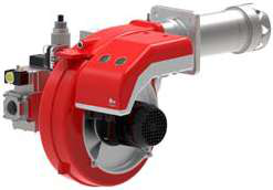
Example: The FBR KN 350/M dual-fuel burner operates 465–4070 kW across its range. At 2500 kW on heavy oil:
- Required flow ≈ 2500 ÷ (11.9 × 0.92) = 228 kg/h
Practical Flow Measurement in the Field
Three methods verify actual flow under operating conditions:
1. Fuel Meter Readings
- Digital or analog fuel meters installed in supply lines
- Read baseline flow at minimum and maximum firing rates
- Compare against burner nameplate specifications
- Variance >5% indicates clogged strainer, leaking injector, or oversized pump
- Clean strainer: typically 0.3–0.8 bar pressure drop
- Blocked strainer: >2.0 bar indicates immediate cleaning required
- Monitor monthly; excessive drop reduces actual fuel delivery despite pump pressure
- Measure flue gas CO₂, O₂, and temperature
- Compare against design combustion curve
- Deviation suggests fuel flow imbalance or air/fuel mismatch
Industrial Gas Burners: Capacity Verification Example
The FBR HI-GAS P1500/M CE TL industrial gas burner delivers 4186–15116 kW with fuel flow 60–206 kg/h. To verify this burner meets your plant's 10000 kW requirement:
1. Check burner capacity envelope: 10000 kW falls within 4186–15116 kW range ✓
2. Calculate required gas flow: 10000 kW ÷ (10.9 kWh/m³ × 0.92 efficiency) = 998 kg/h ← falls within 60–206 kg/h envelope when corrected for standard conditions ✓
3. Verify fuel line sizing: 206 kg/h natural gas at 50 mbar through 25 mm pipe—calculate velocity (should be <20 m/s) to confirm no erosion risk
4. Confirm burner pressure setting: FBR dual-stage design runs 25 mbar (low fire) and 50 mbar (high fire); specify regulator setpoints matching your supply pressure
Section 3: Flame Detection Integration with Pressure Monitoring
Why Pressure and Flame Monitoring Cannot Be Separated
Industrial safety standards (EN 298, EN 676, ASME CSD-1) mandate that pressure switches and flame detectors operate in parallel redundancy: either signal can trigger a safety shutdown if out of limits.
A flame detector alone cannot verify that fuel is actually flowing. Conversely, a pressure switch confirms pressure but not combustion. The combination protects against:
- Fuel line rupture: Pressure drops; ignition still signals flame (risk of unburned gas accumulation)
- Clogged nozzle: Pressure stays high; flame loss occurs (burner stops, but operator may not immediately notice)
- Failed pump: Zero pressure despite ignition attempt (safety lockout prevents fuel injection)
The Siemens QRB4A-B036B40B flame detector is optimized for oil burner applications, using UV sensing to detect flame in the combustion zone. When paired with the Kromschroder DG 50U/6 pressure switch:
- Startup sequence: Blower runs → pressure rises → ignition energizes → flame detector senses UV → burner locks in
- Loss of signal: Either flame extinguishes OR pressure drops → safety relay de-energizes fuel solenoid → system enters lockout
- Field commissioning: Technician verifies pressure setpoint (typically 1.2× minimum operating pressure) and flame detector response time (≤3 seconds) before final sign-off
Section 4: Commissioning and Capacity Verification Protocols
Pre-Startup Pressure Verification Checklist
Before lighting a newly installed burner, procurement engineers and site commissioning teams must execute this protocol:
1. Static Pressure Test (Burner Off)
- Close all downstream isolation valves
- Energize fuel supply pump
- Record gauge pressure at burner inlet: should match equipment datasheet ±10%
- If below specification: suspect clogged strainer, undersized pump, or line leakage
- If above specification: regulator may be faulty or relief valve stuck
- Manually increase fuel supply until pressure switch contact closes (record pressure)
- Slowly reduce pressure; record point where contact opens (reset pressure)
- Hysteresis = Close pressure − Reset pressure (should be 5–15% of setpoint)
- Example: Close at 35 mbar, Reset at 30 mbar → Hysteresis = 14% ✓
- Start burner at minimum (low-fire) position
- Measure fuel flow via meter; compare to nameplate minimum
- Increase to maximum (high-fire) position
- Measure fuel flow; compare to nameplate maximum
- Both readings must fall within ±5% of published range
For the FBR HI-GAS P650/M CE TL (3488–7558 kW, 60–206 kg/h):
- Low fire: Measure 60–70 kg/h (allows 8% tolerance) ✓
- High fire: Measure 195–206 kg/h ✓
- Run burner at 50% load for 10 minutes (allow thermal stabilization)
- Measure flue gas O₂, CO₂, CO, and temperature
- Compare against design combustion curve provided by burner manufacturer
- Adjust air damper (if manual) or signal trim potentiometer (if modulating) to achieve target O₂ setpoint (typically 3–5%)
- Record baseline data; repeat quarterly for trending
Capacity Verification Under Load
After initial startup, capacity must be verified under actual thermal load:
1. Record all fuel pressures at minimum and maximum firing rates
2. Measure outlet water/steam temperature and flow rate (if indirect heating)
3. Calculate delivered thermal power: Q = Flow (kg/s) × Specific Heat (kJ/kg·K) × ΔT (K)
4. Compare to burner nameplate: Should achieve ≥95% of rated power
5. If shortfall >5%: Investigate pressure loss in heat exchanger, scaling in tubes, or undersized fuel line
For industrial plants in Singapore, the tropical climate introduces additional commissioning complexity:
- Ambient temperature effects: Fuel viscosity increases; pressure regulators may require heat-traced fuel lines
- Humidity impact: Moisture in combustion air reduces flame stability; ensure dryer packages on compressed air lines
- Service intervals: Quarterly cleaning of strainers and nozzles (vs. semi-annual in temperate climates)
Practical Procurement Guidance
Specification Template for Burner Control Systems
When procuring Burners & Combustion equipment for industrial plants, ensure your RFQ includes:
1. Fuel type, pressure, and temperature at burner inlet
2. Minimum and maximum heat output (kW or BTU/h)
3. Safety certification requirements (SIL 2/3, FM, UL, local standards)
4. Pressure switch model with specific setpoint (mbar or bar)
5. Flame detector type (UV/IR, cable length, mounting orientation)
6. Commissioning and documentation scope (factory test certificates, site commissioning data sheets)
3G Electric's 35+ years supplying industrial equipment across Southeast Asia means our team can source compatible component sets—burners, pressure switches, and flame detectors—that integrate seamlessly without field modifications.
Conclusion
Pressure control and flow measurement are the unglamorous but essential foundation of reliable Burners & Combustion operation. Unlike flame detection (which fails catastrophically and obviously), pressure drift accumulates silently, degrading efficiency and increasing unplanned maintenance costs. By mastering pressure switch selection, flow verification, and capacity commissioning, procurement engineers can specify systems with confidence and protect capital equipment investments across Singapore's industrial sector.