Introduction: Multi-Fuel Flexibility in Modern Burners & Combustion Systems
Burners & Combustion technology has evolved significantly beyond single-fuel applications. Today's procurement engineers face decisions that extend beyond immediate heating requirements—facilities must account for fuel supply volatility, regional availability differences, and the need to scale operations without complete system replacement. Drawing on 35+ years of industrial equipment distribution experience, 3G Electric recognizes that the most successful burner deployments combine multi-fuel capability with modular architecture that permits capacity expansion as production demands increase.
Unlike traditional single-stage burners, modern dual-fuel and modular systems allow facilities to transition between fuel types, maintain operational continuity during supply interruptions, and add capacity through staged burner integration rather than wholesale infrastructure replacement. This guide addresses the procurement considerations, technical specifications, and integration strategies that enable facilities across diverse geographic regions to optimize both immediate performance and long-term operational resilience.
Section 1: Multi-Fuel Burner Capability and Fuel Switching Architecture
Understanding Dual-Fuel and Switchable Systems
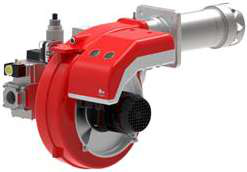
Multi-fuel burners support automatic or manual switching between gas and oil, addressing regional fuel availability constraints and supply chain vulnerabilities. The FBR KN 350/M exemplifies this architecture—a heavy oil burner with dual gas/oil capability delivering 465–4070 kW across two modulating stages. This flexibility proves critical in geographic regions where natural gas availability fluctuates seasonally or where backup fuel redundancy is mandated by operational standards.
When evaluating multi-fuel systems, procurement engineers must assess:
- Fuel switchover reliability: Automatic detection systems that verify fuel availability and switch without process interruption
- Burner head compatibility: Whether the combustion chamber and atomization system support both fuel viscosities and ignition characteristics
- Control system logic: Safety interlocks that prevent simultaneous fuel feed and verify flame presence before pressurizing secondary fuel lines
- Maintenance accessibility: Ease of swapping fuel nozzles, cleaning screens, and accessing fuel filters without extended downtime
The dual-stage design of the FBR KN 350/M enables two-position modulation—full capacity on primary stage, reduced capacity on secondary stage—allowing load matching during lower-demand periods without cycling the ignition system repeatedly. This staged approach reduces thermal stress on burner components and extends service intervals.
Procurement Considerations for Multi-Fuel Selection
When specifying multi-fuel capacity, quantify your facility's actual fuel switching frequency and regulatory requirements. If you operate in a region with stable natural gas supply, a gas-only burner typically offers better thermal efficiency and lower acquisition cost. If you face seasonal interruptions or supply constraints, dual-fuel capability justifies the additional 15–20% equipment cost through operational continuity and reduced emergency response costs.
Document fuel specification requirements: viscosity grades, sulfur content limits, water contamination thresholds, and seasonal availability windows. These parameters drive nozzle selection, combustion air preheating requirements, and maintenance scheduling. 3G Electric's technical team can correlate your regional fuel profiles with compatible burner models to ensure long-term reliability.
Section 2: Capacity Scaling and Modular Burner Integration
Staged Capacity Expansion Without Full System Replacement
Many procurement engineers face growth scenarios where initial heating capacity proves insufficient within 3–5 years. Rather than replacing entire combustion systems, modern modular burner architectures support parallel or sequential installation of additional burner units on shared furnaces or boilers. This staged approach distributes capital investment across multiple budget cycles and minimizes production disruption during expansion phases.
The FBR HI-GAS P550/M CE TL, FBR HI-GAS P650/M CE TL, and FBR HI-GAS P1500/M CE TL represent a product family spanning 2325–15116 kW, enabling procurement of appropriately sized capacity at each expansion stage. Starting with the P550/M (2325–6395 kW) for initial operations, a facility can add a P650/M (3488–7558 kW) within 18 months as demand grows, then a P1500/M (4186–15116 kW) for peak capacity—all operating from shared fuel supply infrastructure and coordinated via common control systems.
Technical Requirements for Multi-Burner Integration
When planning staged capacity expansion, specify these integration features during initial procurement:
- Manifold-based fuel distribution: Fuel headers designed to accept parallel burner connections with individual shutoff valves for isolating failed units without full system shutdown
- Coordinated combustion air supply: Blower systems or ducting scaled to support sequential burner startup without pressure fluctuations that disrupt flame stability
- Common control platform: Master control relays that sequence burner ignition, monitor flame presence across all burners, and execute coordinated shutdown if any unit develops faults
- Modulating linkage compatibility: Burners calibrated to modulate in parallel so that control signals reduce all burners proportionally, maintaining stable pressure and thermal output
The FBR GAS X3/2 CE-LX4 TL Cl. 4 serves smaller capacity requirements (23–174 kW) and demonstrates how product families accommodate diverse scale applications—a facility might deploy a GAS X3/2 for zone heating while scaling to HI-GAS P-series units for main furnace capacity.
Economic Analysis: Staged vs. Single-Stage Procurement
Compare total cost of ownership across three scenarios:
1. Single large burner: Purchase full-capacity unit immediately (highest upfront cost, lowest ongoing utility cost if fully utilized, risk of oversizing during early operations)
2. Staged approach: Start with mid-range burner, add larger units as demand increases (distributed capital expenditure, flexibility to adjust expansion pace based on market conditions, potential for improved efficiency through selective unit operation)
3. Redundancy model: Deploy two identical mid-range burners for full capacity with automatic switchover (higher initial cost offset by elimination of single-point failure, improved preventive maintenance scheduling)
For most industrial applications, staged deployment reduces first-year capital requirements by 40–60% while preserving the option to scale further if business conditions change. Regional fuel costs, facility footprint constraints, and regulatory standby power requirements influence the optimal scenario for your operation.
Section 3: Control System Architecture for Multi-Burner Operations
Coordinating Flame Detection and Safety Interlocks Across Multiple Burners
Modern multi-burner systems require sophisticated control logic that monitors flame presence on each individual burner while preventing simultaneous fuel supply to multiple ignition paths. This architecture demands:
- Individual flame sensors: UV or infrared detectors on each burner's combustion chamber, wired to separate input channels on the master control relay
- Sequential ignition logic: Control programs that energize burner solenoid valves in defined sequence—primary burner must establish stable flame before secondary burner ignition is permitted
- Cross-fault logic: If primary burner loses flame while secondary burner is operating, control system must immediately shut down the secondary unit and attempt re-ignition of the primary—preventing unsafe operation with only partial capacity
- Cumulative timer logic: Total ignition attempts across all burners limited to prevent repeated cycling that strains ignition electrodes and fuel pumps
Operator Interface and Load Demand Signaling
When integrating multiple burner units, specify control systems that accept continuous load demand signals (4–20 mA analog or 0–10 V modulating commands) and distribute load proportionally across available burners. This architecture enables:
- Staged capacity utilization: As furnace demand increases, master control energizes burners sequentially (primary at 100%, add secondary if demand exceeds 70% of primary capacity)
- Load balancing: Operating hours and burner cycling distributed equally to extend service intervals uniformly across all units
- Efficiency optimization: Burners sized so that any single unit operates in the 50–100% range during normal duty, avoiding inefficient part-load operation below 40% capacity
Document the facility's actual demand profile—peak hourly load, average load, minimum stable load—so that burner selection and sequencing logic align with real operational patterns. Many facilities discover that their 3–5 year average demand justifies a mid-range burner with occasional reliance on a smaller backup unit, rather than oversizing to worst-case peak demand.
Section 4: Procurement Specifications and Vendor Coordination
Creating Technical Data Packages for Burner Selection
Supply 3G Electric's procurement specialists with:
- Fuel specifications: Type (natural gas, propane, heavy oil, residual oil), heating value (BTU/scf or BTU/lb), sulfur content limits, pressure ranges at burner inlet
- Combustion air conditions: Ambient temperature range, altitude, humidity extremes, particulate environment (if preheated air, specify heater capacity)
- Thermal demand profile: Peak hourly requirement (kW), annual average requirement, minimum stable load, seasonal variation patterns
- Physical constraints: Available burner floor space, furnace throat opening dimensions, electrical supply voltage/phase/frequency, control signal compatibility with existing systems
- Regulatory requirements: Emission standards (NOx limits in ppm), sound level limits (dB), pressure equipment directive compliance, regional certification mandates
With 35+ years of global equipment distribution, 3G Electric maintains familiarity with region-specific certification pathways—CE marking requirements for Europe, CSA/UL standards for North America, and compliance documentation for Asian markets—enabling efficient procurement across multi-region facilities.
Lifecycle Cost Analysis: Service Parts Availability and Warranty Terms
During vendor evaluation, extend your analysis beyond purchase price:
- Service parts lead times: Specify maximum acceptable delivery windows for replacement nozzles, electrodes, fuel filters, and control relays. Facilities in remote regions may require higher stock reserves
- Warranty scope: Clarify coverage for defects in materials vs. wear items (electrodes, seals, burner head inserts typically considered wear items with shorter warranty periods)
- Preventive maintenance intervals: Obtain documented schedules for nozzle cleaning, filter replacement, and electrode inspection. Budget accordingly—typical industrial burners require 6–12 month maintenance intervals depending on fuel quality
- Spare parts availability: Confirm that replacement components are stocked or available within 5 business days. Some manufacturers consolidate spare parts distribution to regional warehouses, impacting delivery times
3G Electric maintains direct relationships with major burner manufacturers (FBR, Riello, Weishaupt, Baltur) and stocks critical wear items, ensuring rapid deployment of replacement components to minimize facility downtime.
Integration Testing and Commissioning Support
When deploying multi-burner systems or scaling existing capacity, budget for on-site commissioning support:
- Combustion analysis: Professional measurement of flue gas O₂, CO, and CO₂ content to verify stoichiometric air-fuel ratio and detect combustion inefficiencies before operation begins
- Control system verification: Testing of flame detection, fuel valve sequencing, and safety shutdowns under actual load conditions
- Operator training: Documented procedures for normal startup/shutdown, load modulation, emergency procedures, and routine maintenance tasks
- Documentation package: As-built control schematics, burner performance curves under actual operating conditions, calibration certificates, and warranty registration
Proper commissioning typically requires 1–2 days on-site and prevents months of operational inefficiency and unplanned downtime. 3G Electric coordinates with customer maintenance teams to develop customized commissioning plans aligned with facility schedules and capabilities.
Conclusion: Strategic Procurement for Flexible, Scalable Burners & Combustion Systems
Successful Burners & Combustion procurement extends beyond selecting the lowest-cost unit—it requires alignment of burner capacity, fuel flexibility, and control architecture with your facility's realistic growth trajectory and regional operating constraints. Multi-fuel capability provides insurance against supply disruptions, while modular capacity architecture distributes capital investment across multiple budget cycles and permits responsive scaling to market demand.
Partner with 3G Electric to develop comprehensive procurement strategies that balance immediate performance requirements with long-term operational resilience. Our 35+ years of industrial equipment distribution experience across global markets ensures you receive technically optimized solutions matched to your specific fuel profile, regulatory environment, and growth objectives.