Understanding Burners & Combustion Noise and Vibration Sources
Industrial burners generate noise across multiple frequency bands—low-frequency combustion rumble (20–100 Hz), mid-range mechanical vibration (100–500 Hz), and high-frequency air turbulence (500+ Hz). In Singapore's demanding industrial environment, where plants operate 24/7 under tropical heat stress, uncontrolled noise and vibration accelerate bearing degradation, loosen fasteners, and compromise flame detection accuracy.
Burner combustion noise stems from three primary mechanisms: turbulent fuel-air mixing, pressure oscillations within the combustion chamber, and mechanical vibration transmitted through the burner frame into mounting structures. Singapore's occupational health regulations (WSH Act) mandate noise levels below 85 dB(A) for 8-hour exposure. Failing to manage noise creates both compliance liability and hidden maintenance costs.
With over 35 years of industrial equipment distribution experience, 3G Electric has supported Singapore's maintenance teams through thousands of burner installations and retrofits. Noise and vibration management is where field experience translates into measurable uptime gains—a 3–5 dB reduction in burner noise often correlates with 15–20% longer bearing life and improved safety relay response times.
Noise Isolation and Mounting Strategies
Vibration Isolation Fundamentals
Burner mounting directly impacts noise transmission into the plant structure. Rigid steel mounting brackets create a direct acoustic bridge; vibration propagates freely into the boiler, ductwork, and building frame. Effective isolation requires a three-layer approach:
1. Elastomeric Isolation Pads – Use natural rubber or neoprene pads rated for the burner's operating weight and thermal conditions. In Singapore's 28–35°C ambient temperatures, thermally stable elastomers prevent pad degradation. Pads must be sized to achieve 5–8 Hz natural frequency, lower than the burner's dominant noise frequencies (40–200 Hz).
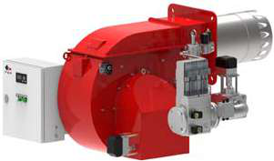
2. Spring-Damper Mounts – For burners delivering 2325–15,116 kW (like FBR HI-GAS P1500/M CE TL), springs with integral dampers provide load-dependent frequency tuning. Spring constants must match the burner's static load; undersizing results in resonance amplification, oversizing reduces isolation effectiveness.
3. Flexible Fuel and Air Lines – Hard-pipe connections bypass vibration isolation. Install 300–600 mm flexible hose sections (braided stainless steel or reinforced rubber) between the burner and rigid piping systems. This breaks the mechanical coupling that transmits combustion vibration into the supply manifold.
Practical Commissioning Protocol
After burner installation, baseline vibration measurements at the burner frame, fuel manifold, and mounting structure establish your noise signature. Use a handheld vibration analyzer (acceleration units: m/s²) at three orthogonal axes. Ideal targets for industrial burners: <2.8 m/s² at the mounting feet, <1.4 m/s² at the boiler casing. If measurements exceed these thresholds, incrementally add isolation material and re-measure.
For high-capacity burners like the FBR HI-GAS P550/M CE TL (2325–6395 kW), vibration can couple into the boiler's acoustic modes, creating standing wave resonances. Adding absorption material (rockwool or fiberglass blankets) 50–100 mm around the combustion chamber and burner throat reduces secondary noise by 3–6 dB without affecting combustion efficiency.
Flame Detection and Noise-Related Safety Faults
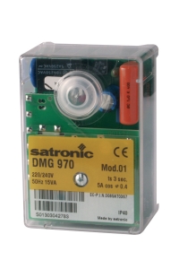
High vibration and acoustic noise degrade sensor performance. The Satronic Relay DMG 970-N MOD.01 flame detection module operates on UV or IR flame signal strength; vibration-induced microphonic effects and electromagnetic coupling from noisy equipment generate false lockout events.
Electromagnetic Shielding for Control Relays
Place the control relay enclosure 1–2 meters from the burner on a dedicated vibration-isolated mounting bracket. Shield the flame detector signal cable with twisted-pair, shielded cabling grounded only at the relay enclosure end (single-point grounding). In Singapore's high-humidity environment, use stainless steel conduit for cable runs near steam lines or water sprays—corrosion compromises the shield connection and introduces common-mode noise.
Combustion noise >90 dB(A) near the flame detector can induce 30–50 mV false signals on unshielded cables, exceeding the noise margin of older relay modules. Modern control relays include software noise filtering; verify that the DMG 970-N firmware revision supports adaptive threshold adjustment if baseline noise >85 dB(A).
Sensor Separation and Mounting
Mount the UV or IR flame detector rod perpendicular to the vibration axis of the burner gun. If the burner oscillates horizontally (common with side-mounted burners), mount the detector vertically to minimize microphonic coupling. Secure the detector tube with rubber-lined clamps rather than rigid metal brackets; this decouples vibration before it reaches the photodiode element.
For dual-fuel systems like the FBR KN 350/M (465–4070 kW), which switches between gas and heavy oil, verify flame detection stability across both fuel modes. Oil combustion generates more soot and smoke, scattering the flame signal; ensure the detector window is shielded from soot fouling with a sight glass protector or ceramic tube.
Preventive Maintenance Schedules and Vibration Trending
Monthly Inspection Protocol
- Visual Check: Inspect all mounting bolts for looseness (use a torque wrench to re-tighten at 80% of catalog specification). Loose fasteners introduce microslip, radiating high-frequency noise (500+ Hz).
- Elastomer Assessment: Press on isolation pads with hand pressure. Cracked or permanently compressed elastomers indicate replacement need (typically 18–36 month life in tropical climates).
- Flexible Hose Condition: Look for cracks, bulging, or separation of braid layers in fuel and air hoses. Environmental ozone and thermal cycling (common in Singapore's industrial zones) degrade rubber faster than in temperate regions.
Conduct FFT (Fast Fourier Transform) vibration spectra at the burner mounting frame. Trending analysis reveals developing faults:
- Bearing wear: Increases broadband vibration (5–10 kHz range) and sub-harmonic frequencies below the running speed.
- Combustion instability: Shows as sharp peaks at combustion frequency and harmonics (e.g., if the burner fires at 50 Hz, peaks appear at 50, 100, 150 Hz).
- Loose components: Generates discrete peaks at the mechanical run frequency and multiples; loose burner nozzles or air register plates show this signature.
If vibration levels increase >30% from baseline over three consecutive quarters, schedule a full burner inspection (nozzle gap, ignition electrode wear, air register alignment).
Documentation and Predictive Maintenance
Maintain a digital log of vibration measurements, noise recordings, and service intervals. Many Singapore maintenance teams use cloud-based CMMS platforms (Computerized Maintenance Management Systems) to correlate vibration trends with fuel consumption efficiency. A 2–3% drop in fuel efficiency often precedes a 5+ dB noise increase by 4–8 weeks, providing actionable advance warning.
Integration with 3G Electric's Support Network
With 35+ years distributing industrial equipment across Singapore and Southeast Asia, 3G Electric supplies both the burner hardware and the diagnostic tools that maintenance teams rely on. Our inventory includes replacement isolation mounts, flexible hose assemblies, and Satronic control relay modules—critical components for effective noise control programs.
When commissioning large-capacity burners like the FBR HI-GAS P1500/M CE TL (4186–15,116 kW), engage our technical team early to specify custom mounting solutions tailored to your plant's acoustic environment and thermal profile. We coordinate with field engineers to establish baseline noise signatures and commissioning acceptance criteria that align with both WSH regulations and your internal uptime targets.
Our technical library includes application notes for the FBR HI-GAS P650/M CE TL and dual-fuel burner configurations, covering noise mitigation in combined heat-and-power (CHP) installations, district heating plants, and process industry boilers. These resources help your team move from reactive noise complaints to proactive, data-driven maintenance.