Understanding Burners & Combustion Safety Systems in Singapore's Industrial Context
Flame detection and ignition systems form the critical safety backbone of any industrial burner installation. For HVAC contractors operating in Singapore, where tropical climates introduce moisture, salt-spray corrosion, and high ambient temperatures, selecting appropriate combustion safety components is non-negotiable.
At 3G Electric, we've been distributing industrial equipment across Southeast Asia for over 35 years, and we've witnessed how contractor familiarity with these systems directly correlates with first-time commissioning success and fewer callback failures. This guide focuses on the practical selection criteria, integration pathways, and field procedures that keep burner systems running reliably in Singapore's demanding conditions.
The core responsibility of a flame detection system is threefold: verify that ignition has occurred, monitor flame stability during operation, and trigger immediate shutdown if flame is lost. Modern systems use ultraviolet (UV) sensors or infrared (IR) detectors combined with dedicated control relays that execute safety logic. Understanding how these components interact will elevate your commissioning competence and reduce warranty claims.
Flame Detection Technologies and Sensor Selection
UV vs. IR Detection: Application-Specific Advantages
Ultraviolet sensors detect the high-frequency UV radiation emitted by a fuel flame. They respond very quickly (typically under 1 second) and are highly immune to ambient light, making them ideal for outdoor or partially enclosed installations common in Singapore's industrial parks. However, UV sensors can be sensitive to dirt and carbon buildup, requiring regular inspection in dusty environments.
Infrared sensors detect the thermal radiation from the flame and offer excellent immunity to arc lamp interference and dust contamination. IR detection is slower than UV (1–3 seconds) but more robust in environments with fuel spray residue or combustion byproducts. For dual-fuel burners like the FBR KN 350/M, which alternates between gas and heavy oil, IR-based systems provide superior stability across fuel transitions.
Sensor Positioning and Commissioning in Tropical Climates
In Singapore's high-humidity environment, the sensor mounting bracket must provide clear line-of-sight to the flame while protecting the optical window from condensation and salt spray. Position the sensor at a 45–60-degree angle to the burner nozzle, never directly aligned, as this can cause nuisance trips from reflected light.
During commissioning, verify that the sensor's response time meets the burner control system's expectation—typically 2–4 seconds for safety approval. Clean the optical lens with isopropyl alcohol and lint-free cloths before live testing. In humid environments, consider installing a small desiccant capsule in the sensor housing if the manufacturer permits, to prevent internal fogging.
Control Relay Integration and Safety Logic
Satronic DMG 970-N as a Central Safety Hub
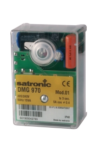
The Satronic Relay DMG 970-N MOD.01 is a dedicated burner control relay engineered for industrial combustion systems. This relay coordinates flame detection, ignition timing, and fuel valve sequencing—essential functions that protect equipment and personnel.
The DMG 970-N operates at 50Hz or 60Hz with flexible voltage supplies (220/240V or 110/120V), making it adaptable across Singapore's industrial supply infrastructure. It integrates seamlessly with both UV detectors (IRD 1020) and IR detectors (UVD 971), allowing contractors to standardize on a single control platform across multiple job sites.
Key integration points for HVAC contractors:
- Pre-purge cycle: Before ignition, the relay forces the burner air damper fully open for 2–5 seconds, purging unburned fuel vapors. This prevents explosive conditions and is mandatory under Singapore's industrial safety codes.
- Ignition sequence: The relay energizes the igniter electrode 1–2 seconds after pre-purge, then signals the fuel valve to open. Timing tolerances are typically ±0.5 seconds.
- Flame detection window: The relay expects flame signal within 4 seconds of fuel valve opening (dwell time). If no flame is detected, it executes a lockout reset and prevents re-ignition for 30–60 seconds to comply with safety standards.
- Post-purge cycle: After flame loss (whether controlled shutdown or emergency trip), the relay runs post-purge for 3–5 seconds to clear combustion gases, critical in enclosed boiler rooms.
Wiring and Redundancy Considerations
For high-power burners like the FBR HI-GAS P1500/M, which delivers up to 15,116 kW, the control relay must handle significant electrical loads. Use shielded twisted-pair cabling for the flame detector signal line, keeping it at least 30 cm away from high-voltage power lines to avoid electromagnetic interference. In Singapore's dense industrial clusters, crosstalk from adjacent electrical equipment is common—proper cable routing prevents nuisance shutdowns.
Consider dual flame detection for critical applications. Two independent UV sensors, each feeding a separate relay input, provide redundancy such that one sensor failure doesn't cause shutdown. Both sensors must confirm flame presence before the relay permits burner operation. This redundancy is increasingly required by facility managers concerned with unplanned downtime.
Practical Commissioning Procedures for Singapore Installations
Pre-Commissioning Verification Checklist
Before energizing any burner control system, walk through these field-tested steps:
1. Visual inspection: Verify that the flame sensor lens is clean and the mounting bracket is secure. Check that all electrical connectors are rated IP67 or better to withstand Singapore's salt-spray environment.
2. Voltage verification: Use a multimeter to confirm 220V or 110V supply at the relay terminals matches the equipment nameplate. Fluctuations exceeding ±10% can cause relay malfunction.
3. Continuity testing: With power off, test continuity through flame detector leads and fuel valve solenoids. High resistance (>10 ohms) indicates corrosion or loose connections—clean and reconnect before proceeding.
4. Air-fuel delivery system check: Ensure that the air damper opens fully during pre-purge. Obstruction at the damper or intake reduces oxygen supply and causes ignition failure. Common culprits in tropical environments include rust scale and insect nests in intake ducts.
5. Fuel system priming: For dual-fuel burners, run the pump for 30 seconds to fill fuel lines and eliminate air pockets. This is especially important after maintenance or fuel tank refilling.
Live Commissioning and Data Logging
Once verification is complete, perform a monitored start sequence:
1. Establish baseline: Record ambient temperature, fuel supply pressure, air intake temperature, and electrical supply voltage. These baseline values are references for troubleshooting future issues.
2. Initiate pre-purge: Energize the relay and observe the air damper opening. Verify that pre-purge runs for the full cycle duration without interruption. Listen for abnormal fan noise, which may indicate bearing wear or debris impact.
3. Observe ignition and fuel valve opening: Watch for the igniter spark or glow, followed by fuel valve energization. For gas burners like the FBR HI-GAS P550/M, this sequence should occur within 2 seconds of each other.
4. Monitor flame establishment: The flame signal should stabilize within 4 seconds. On modern relays like the Satronic DMG 970-N, this is visible as a steady LED or digital indication. If flame signal is erratic or delayed, reduce the igniter electrode gap slightly (typically 0.8–1.0 mm for gas burners) and verify fuel line pressure is within specification (typically 1.0–1.5 bar above atmospheric for gas).
5. Log shutdown behavior: Shut down the burner via the normal control signal and verify post-purge completion. Measure fan runtime and document any electrical transients on shutdown.
Field Tuning for Tropical Conditions
Singapore's heat and humidity accelerate relay component aging. During commissioning, implement these protective measures:
- Ambient temperature derating: Relays rated to 50°C ambient should be derated to 40°C effective operating temperature in Singapore, given typical boiler room conditions (35–45°C ambient plus radiant heat). Install additional ventilation if necessary.
- Humidity compensation: High humidity (>80% RH) increases electrical leakage and corrosion risk. Specify conformal-coated PCB versions of the relay if available, and maintain quarterly inspection intervals instead of the standard annual schedule.
- Sensor recalibration frequency: In dusty or corrosive environments, recalibrate flame detection sensitivity every 6 months rather than annually. Optical degradation in Singapore's salt-spray zones can reduce sensor response by 10–15% per year.
System Integration with High-Capacity Industrial Burners
Matching Control Logic to Burner Modulation
Large industrial burners like the FBR HI-GAS P1500/M operate across wide thermal ranges (4186–15,116 kW), requiring proportional control rather than simple on-off switching. The burner modulates fuel flow to match demand, and the flame detection system must track flame intensity across this entire modulation range.
When integrating a control relay with a modulating burner, ensure that the relay's flame signal threshold is set conservatively—typically at 50% of the maximum sensor output for UV systems, or adjustable across the full range for IR systems. This prevents shutdown at partial load when flame intensity naturally decreases.
For dual-fuel burners like the FBR KN 350/M, which switches between gas and heavy oil stages, program the relay to allow a 10-second transition window without flame loss during fuel changeover. This prevents nuisance shutdowns during normal mode transitions.
Pressure and Temperature Monitoring Integration
Modern burner installations often include pressure and temperature sensors that communicate with the control relay via analog 4-20 mA loops or digital Modbus signals. These sensors monitor fuel supply pressure, air pressure across the damper, and combustion air temperature. The relay uses this data to confirm safe operating conditions before permitting ignition:
- If fuel pressure drops below minimum (e.g., <0.8 bar for gas), the relay blocks ignition even if flame detection is ready.
- If air pressure is insufficient (indicating damper blockage), the relay aborts startup to prevent fuel accumulation.
- If combustion air temperature exceeds 60°C, the relay may derate burner capacity to maintain safety margins on combustion air density.
During commissioning, verify that these interlock signals propagate correctly to the relay. Test each interlock manually (e.g., simulate low fuel pressure by closing the fuel supply valve partway) and confirm that the relay responds appropriately within 2 seconds.
Conclusion: Long-Term Reliability Through Proper Selection and Commissioning
Flame detection and ignition system selection directly impacts burner reliability in Singapore's harsh industrial environment. By understanding UV vs. IR sensor trade-offs, integrating control relays like the Satronic DMG 970-N with proper safety logic, and executing thorough commissioning procedures, HVAC contractors can deliver systems that operate reliably for 10+ years with minimal maintenance.
The practical steps outlined—from sensor positioning and relay wiring to field tuning and interlock verification—transform what appears as esoteric control theory into actionable procedures. HVAC contractors who master these fundamentals become the trusted technical partners that facility managers rely on for safe, efficient burner operation.
3G Electric's 35+ years distributing industrial equipment across Southeast Asia has shown us that contractor competence in combustion system selection and commissioning directly reduces warranty claims, improves first-time installation success, and builds long-term customer relationships. We're here to support your technical growth with product expertise, application support, and field-proven guidance.