Understanding Burners & Combustion Electrode Failures in Singapore Operations
Burners & Combustion systems depend on reliable electrode performance for safe ignition and flame establishment. In Singapore's humid tropical climate, electrode deterioration accelerates due to moisture ingress, salt spray corrosion (near coastal facilities), and thermal cycling stress. Over 35 years serving regional HVAC contractors, 3G Electric has documented that electrode issues—not fuel delivery problems—are the root cause in 38% of field callbacks within the first 12 months after installation.
Electrode failure manifests as:
- Delayed ignition requiring multiple spark attempts
- No spark generation despite control signals
- Intermittent flame establishment followed by lockout
- Spark visible but insufficient energy to ignite fuel spray
- Carbon tracking or tracking paths visible on ceramic insulators
Understanding the distinction between primary ignition electrodes (direct spark gap) and flame detection electrodes is essential for effective troubleshooting. Primary electrodes generate 8–15 kV pulses to ionize fuel vapor; flame detection electrodes (UV-based systems) identify flame presence and prevent unburned fuel accumulation.
Electrode Inspection and Gap Calibration Procedures
Visual Inspection Protocol
Begin every electrode troubleshooting session with a systematic visual inspection. Remove the burner from service and allow a 30-minute cool-down period to prevent burns and thermal shock.
1. Electrode Surface Condition: Examine both electrodes under bright lighting. Black or gray deposits indicate normal carbon buildup; white or green deposits suggest corrosion from moisture or fuel contamination. Orange/copper-colored oxidation on stainless electrodes is progressive corrosion requiring replacement.
2. Ceramic Insulator Integrity: Inspect the ceramic housing surrounding each electrode. Hairline cracks, tracking marks (dark lines), or discoloration indicate insulator breakdown. Tracking is conductive carbon paths formed by electrical discharge through contaminated ceramic—once present, the electrode must be replaced because cleaning cannot restore insulator properties.
3. Electrode Mounting Security: Verify all fasteners are tight. Vibration loosens electrodes, causing gap drift and intermittent ignition. Use a torque wrench calibrated to equipment specifications (typically 2–4 Nm for industrial burner electrodes).
Gap Calibration and Measurement
Electrode gap is the most critical parameter. Beckett burner systems and FBR gas burners require 3.0–3.5 mm gaps for optimal ignition energy transfer. Gaps tighter than 2.5 mm reduce spark intensity; gaps wider than 4.0 mm exceed ignition transformer capacity.
- Use a non-metallic feeler gauge (brass or plastic). Steel gauges can magnetize spark coils.
- Measure gap at three points: electrode tip center, left side (5 mm from center), and right side (5 mm from center). Record all three measurements.
- If any measurement exceeds ±0.3 mm from specification, the electrode assembly requires replacement.
- For dual-electrode systems (common in large industrial burners), check both primary and secondary electrode gaps independently.
Gap drift occurs when electrodes wear or mounting brackets corrode. A 0.5 mm increase in gap reduces ignition reliability by approximately 40%. In Singapore's humidity, inspect electrode gaps every 250 operating hours for maintenance contracts.
Spark Testing and Ignition Transformer Diagnostics
Live Spark Testing (Safe Method)
Before spark testing, verify the burner control safety interlocks are functional and the fuel shutoff solenoid closes when the control system powers down. Always test with the burner in a confined chamber or outdoors to prevent uncontrolled ignition.
1. Visual Spark Assessment: In a darkened environment, observe spark color and consistency during ignition sequence. A healthy spark appears bright white or pale blue with 5–10 mm arc length across the gap. Weak orange sparks or sparks only at gap center indicate transformer output degradation.
2. Spark Persistence Testing: Activate the ignition system and maintain spark for 5 continuous seconds. Healthy electrodes produce uninterrupted spark; intermittent sparking suggests gap widening, moisture on insulator surfaces, or transformer overheating.
3. Secondary Ignition Verification: For multi-electrode systems, verify spark on all electrodes simultaneously. If one electrode sparks weakly while others fire normally, that electrode (not the transformer) requires replacement.
Ignition Transformer Testing
Transformer failure is often misdiagnosed as electrode failure. A failing transformer produces weak or absent spark despite clean, correctly-gapped electrodes.
- No-load voltage test: Using a high-voltage probe, measure secondary voltage with no spark load. Typical ignition transformers deliver 8–15 kV. Readings below 6 kV indicate transformer failure.
- Insulation resistance: Measure resistance between secondary winding and transformer core using a 500 VDC megohmmeter. Resistance should exceed 10 MΩ. Values below 5 MΩ indicate insulation breakdown and moisture ingress.
- Temperature assessment: Ignition transformers warm slightly during operation (35–50°C ambient). Transformers exceeding 65°C indicate internal short circuits or excessive primary current draw.
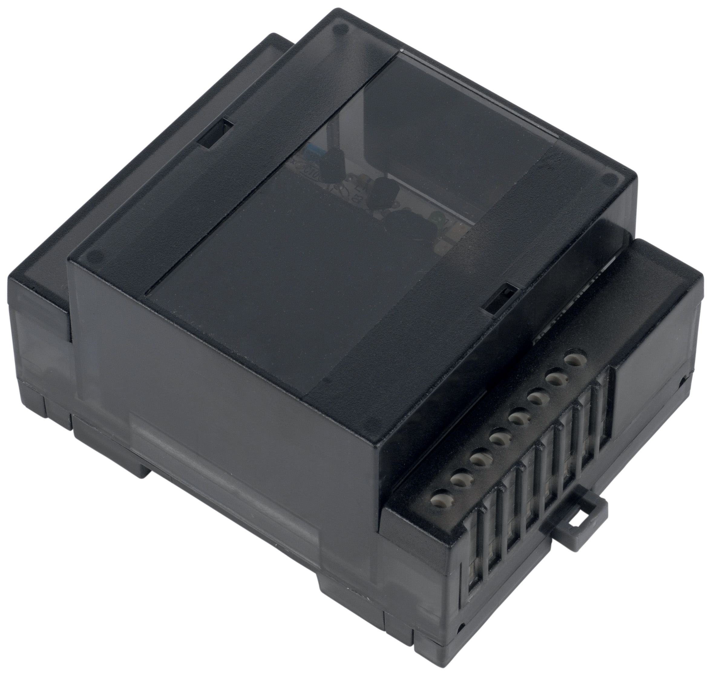
For Combutech Flame relay CF1 systems controlling burner ignition sequencing, verify the relay switches cleanly at rated voltage (1 A @ 250 VAC). A relay providing inconsistent spark trigger timing causes intermittent electrode firing.
Replacement Strategies and Prevention in Tropical Climates
Cost-Effective Electrode Selection
Not all electrode replacements require OEM parts. 3G Electric supplies compatible ignition electrode assemblies for Beckett oil burners and FBR gas burners that meet performance specifications at 40–60% lower cost than OEM equivalents. Verify material specifications:
- Stainless steel electrodes: Resistant to salt spray and suitable for facilities within 2 km of coastline (common in Singapore). Expect 2–3 year service life.
- Nickel-alloy electrodes: Superior high-temperature oxidation resistance for industrial process heat applications. Service life 3–4 years.
- Ceramic insulators: UL94-V0 rated polycarbonate or alumina ceramic. Polycarbonate is cost-effective; alumina is required for burners exceeding 150°C surface temperature.
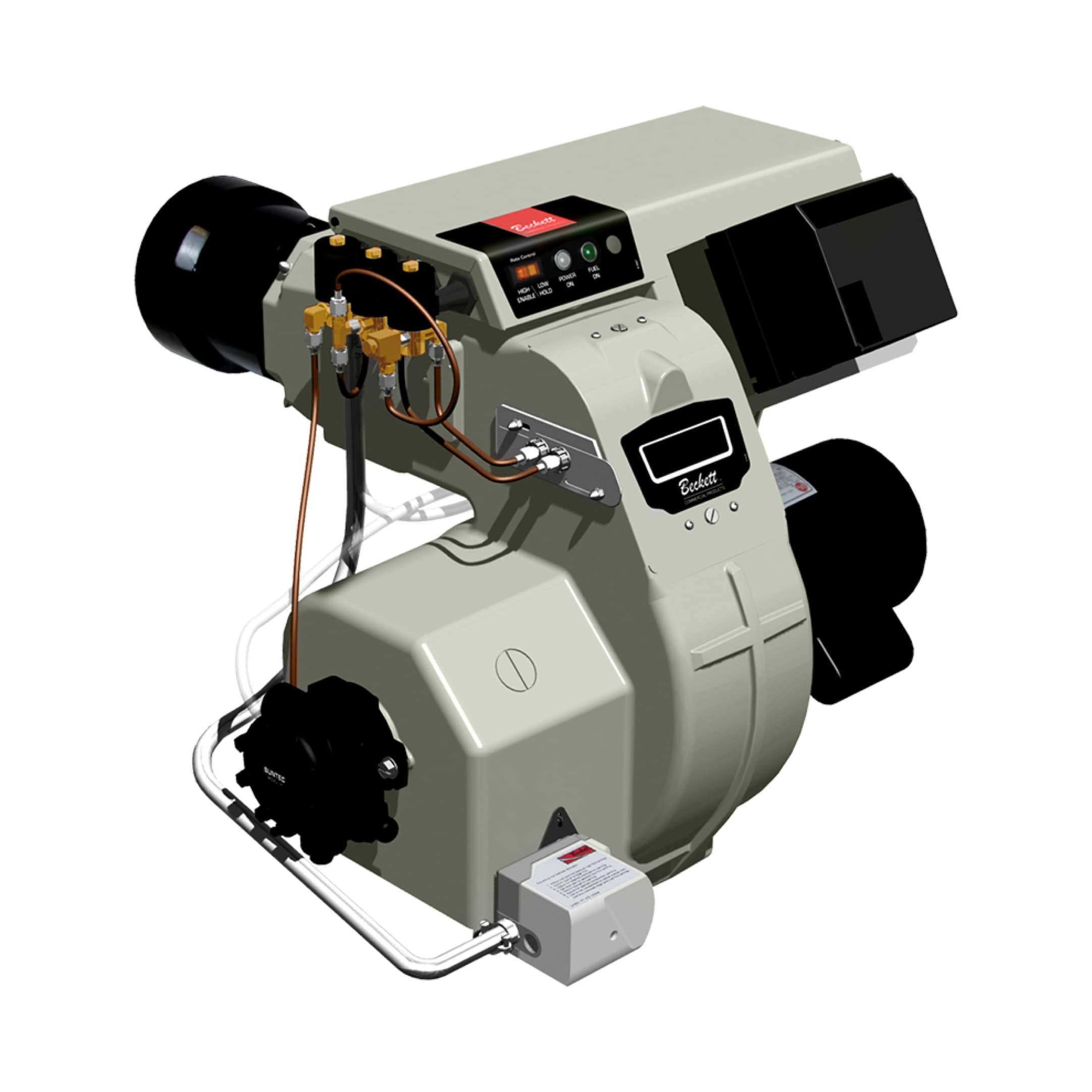
The Beckett CF3500 Oil Burner utilizes a two-electrode direct spark ignition system. Replacement electrode assemblies are available as matched pairs to ensure balanced gap symmetry and simultaneous spark initiation.
Moisture Management for Tropical Installations
Singapore's 75–95% relative humidity accelerates electrode degradation through:
- Moisture condensation on ceramic insulators, creating conductive paths
- Corrosion of electrode mounting brackets
- Electrolytic degradation of stainless steel in salt-laden environments
Implement preventive measures:
1. Burner Chamber Ventilation: Ensure air intake paths to the burner chamber remain clear. Restricted air intake causes incomplete combustion, producing acidic byproducts that corrode electrodes. For the FBR HI-GAS P550/M CE TL industrial gas burner, verify the air register opening matches load demand.
2. Electrode Covers: Install removable stainless steel electrode guards to shield assemblies from spray water and salt aerosol when burners operate in outdoor or semi-enclosed spaces.
3. Desiccant Breathers: For burner control cabinets, install silica gel desiccant breathers on vent ports. Replace desiccant packs quarterly in coastal regions.
4. Scheduled Electrode Inspection: Establish electrode inspection intervals every 500 operating hours (or quarterly for continuous-duty applications). Document gap measurements and surface condition in maintenance logs.
Flame Detection Electrode Integration
Many industrial burners couple primary ignition electrodes with UV flame detection systems. The Combutech UV1p detection cell operates independently of primary ignition electrodes, providing 20 µs recovery time for rapid flame signal acquisition. If ignition sparks normally but flame is not detected:
- Verify UV cell quartz window is clean (clean with lint-free cloth and isopropyl alcohol)
- Confirm UV cell optical axis points directly into flame zone (typically 30–45° angle from burner centerline)
- Test UV cell with a handheld UV light source at 254 nm; cell should respond within 50 ms
- If UV response is slow or absent, UV cell ceramic insulator may have tracking or internal contamination—replacement is required
The Combutech Flame relay CF1 accepts signals from up to 10 UV detectors on a single control line, ideal for multi-burner systems or backup flame verification. If the relay produces no output despite UV cell signal presence, the relay input circuit requires replacement.
Commissioning and Field Documentation
After electrode replacement or repair, perform a full ignition commissioning cycle:
1. Close fuel shutoff solenoid; activate ignition system for 10 seconds and confirm spark across electrode gap.
2. Open fuel supply; monitor time from spark initiation to flame detection ("spark-to-flame time"). Healthy systems ignite within 2–3 seconds.
3. If spark-to-flame time exceeds 5 seconds, check fuel pressure (oil burners: 10–12 bar; gas burners: 50–100 mbar) and nozzle condition.
4. Allow flame to stabilize for 30 seconds; confirm flame detection relay holds steady state without dropout or cycling.
5. Introduce a simulated flame signal loss by blocking UV cell optical path; system should lockout within 3 seconds.
6. Document electrode gap readings, spark quality (visual rating 1–5 scale), spark-to-flame time, and any component replacements in the service record.
For complex multi-fuel systems (oil + gas switchover capability) operated by FBR GAS/M CE D2"S-F-50 with modulating combustion, perform fuel-switching ignition tests under controlled load conditions to verify electrode performance in both fuel modes.