Understanding Burners & Combustion Electrode Gap Fundamentals
Burners & Combustion systems depend critically on precise electrode spacing to establish reliable ignition. The spark gap—typically ranging from 3 mm to 6 mm depending on burner design and fuel type—must be maintained within manufacturer specifications to ensure consistent flame establishment. When electrode gaps drift beyond tolerance, the ignition system requires higher voltage to bridge the space, reducing spark reliability and creating the conditions for hard-start and lockout failures.
With 35+ years of experience distributing industrial heating equipment across Southeast Asia, 3G Electric has documented that electrode gap drift accounts for approximately 18% of intermittent burner failures in Singapore's tropical climate. High humidity, salt-air corrosion, and thermal cycling create accelerated electrode erosion in coastal installations. Understanding the relationship between physical gap spacing, spark energy, and fuel ignition characteristics is essential for systematic troubleshooting.
Diagnostic Procedures for Electrode Condition Assessment
Visual Inspection and Dimensional Measurement
Begin with a comprehensive visual examination of both electrodes before attempting spark testing. Look for the following indicators:
- Erosion patterns: Pitting, rounded edges, or surface cratering indicates thermal stress and oxidation
- Deposit accumulation: Carbon buildup, fuel residue, or corrosion products bridge the gap and prevent spark formation
- Mechanical damage: Cracks, bent tips, or misalignment from thermal shock or installation stress
- Surface discoloration: Blue or copper oxide coating suggests overheating or insufficient air gap clearance
Using a precision spark gap tool (calibrated feeler gauge), measure the electrode separation at three points: center, top, and bottom of the gap. Record baseline measurements and compare against manufacturer specifications listed in the burner control module documentation. Variations exceeding 0.5 mm across the gap indicate electrode bow or mounting degradation requiring corrective action.
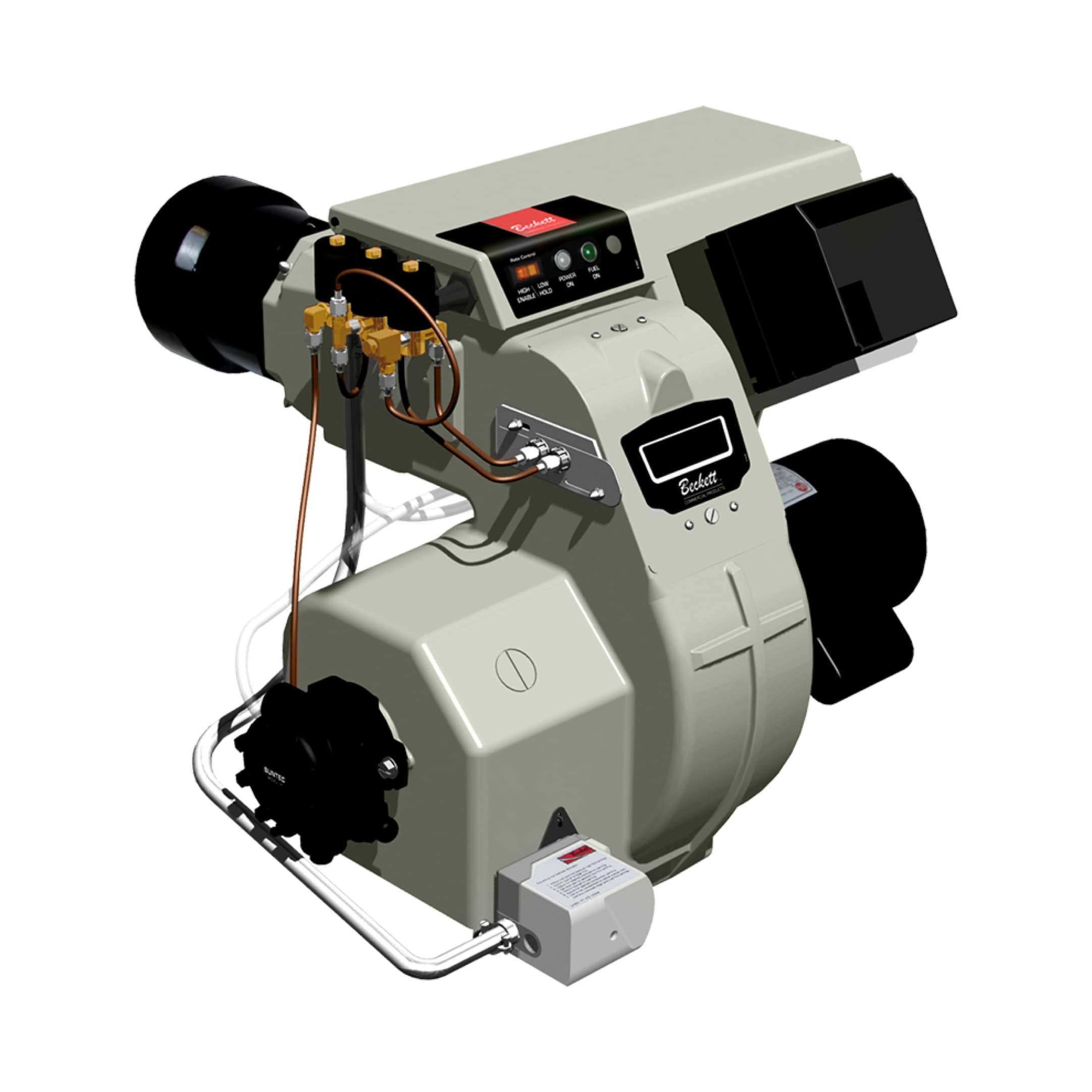
For systems using the Beckett CF3500 Oil Burner with direct spark ignition, maintain electrode gaps within 0.125 inches (3.2 mm) ± 0.05 inches. Gaps exceeding 4 mm significantly reduce spark reliability, particularly in high-altitude installations or systems with aged ignition transformers.
Spark Quality Testing with Voltage and Current Measurement
Electrode condition directly affects spark quality, which can be assessed through direct measurement and visual observation:
1. Primary circuit voltage: Measure transformer output voltage at the spark lead terminals using a digital multimeter (AC setting). Specification should be 9–12 kV RMS for oil burner systems. Voltages below 8 kV indicate transformer aging or winding short-circuits.
2. Spark current measurement: Using a clamp meter capable of detecting spark current (typically 20–40 mA AC), measure current flowing through the spark gap during ignition. Current below 15 mA suggests excessive gap spacing or electrode deposits preventing reliable spark formation.
3. Visual spark observation: In a darkened service area, observe spark color and intensity:
- Healthy spark: Bright blue-white, consistent gap bridging, sharp cracking sound
- Weak spark: Orange or yellow hue, intermittent arcing, faint electrical sound
- No spark: Transformer fault, open ignition cable, or electrode short-circuit
4. Continuity testing: With power disconnected, verify electrode isolation resistance. Resistance should exceed 1 MΩ (1,000,000 ohms) between electrodes and grounded combustion chamber surfaces. Lower values indicate moisture contamination or electrode fouling.
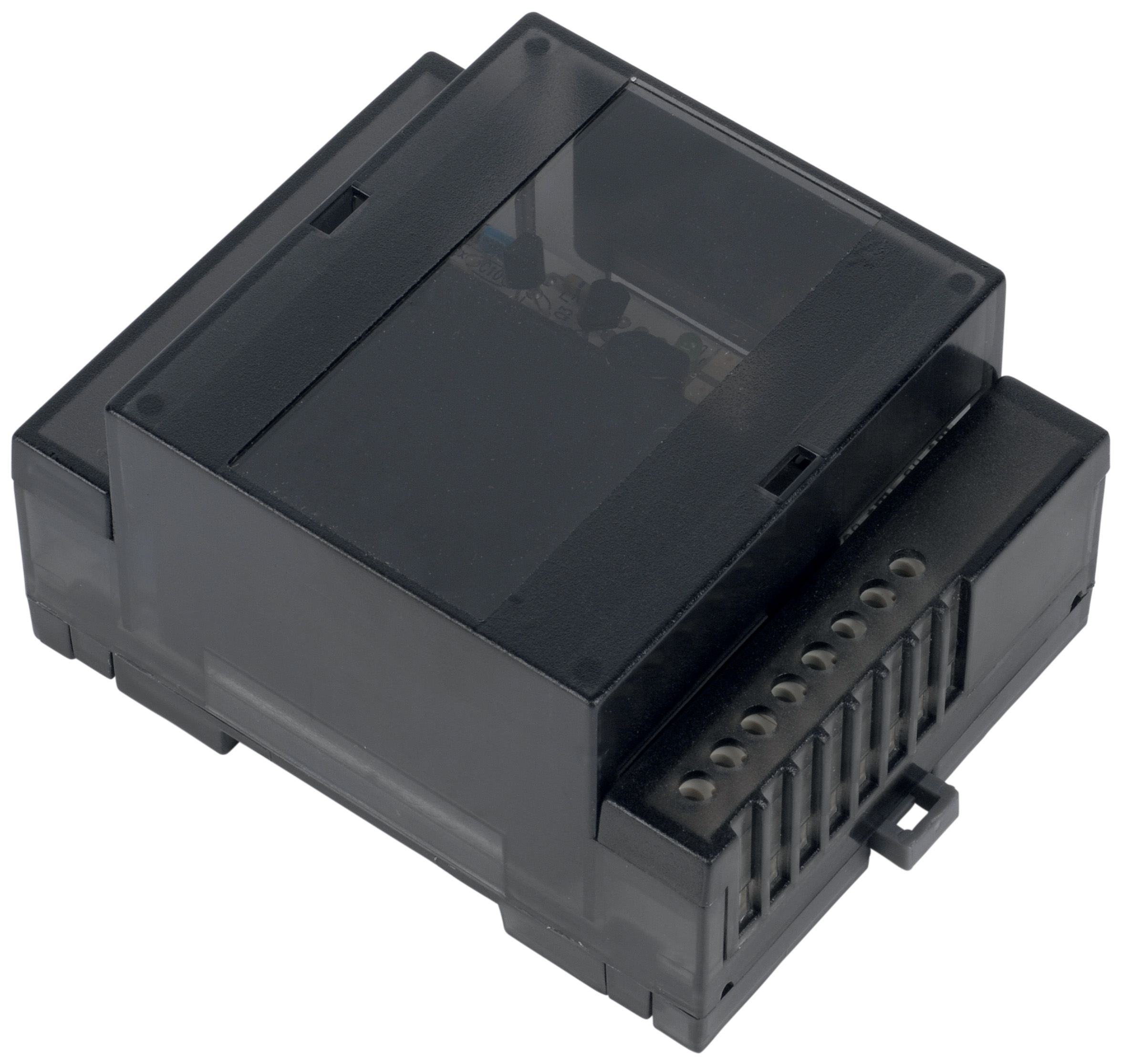
For systems integrating UV flame detection such as the Combutech UV1p detection cell, spark quality defects often manifest as flame detection delays or nuisance lockouts. The UV sensor responds to visible and ultraviolet radiation from the flame, but weak sparks produce insufficient ignition energy, creating delayed flame establishment that exceeds the safety relay detection window.
Corrective Actions and Maintenance Procedures
Electrode Cleaning and Gap Adjustment
When deposits or corrosion are identified, perform the following cleaning sequence:
1. Power isolation: Disconnect the burner from electrical supply and allow the ignition system to discharge (wait 5 minutes minimum)
2. Electrode access: Remove the ignition assembly according to burner-specific service procedures
3. Deposit removal: Use a non-abrasive brass wire brush to gently remove carbon, fuel residue, and oxidation. Avoid scratching the electrode surfaces, as scratches concentrate heat during spark formation
4. Solvent cleaning: Wipe electrodes with a lint-free cloth dampened with isopropyl alcohol to remove remaining residue and moisture
5. Air drying: Allow electrodes to air dry for minimum 10 minutes before reassembly
6. Gap setting: Using the calibrated gap tool, adjust the electrode spacing to manufacturer specifications (typically 3.2–4.0 mm for oil burners). Position the gap tool between electrodes and gently bend the movable electrode until light resistance is felt
After cleaning, spark quality should improve noticeably. Retest voltage, current, and spark appearance before resuming normal burner operation.
Electrode Replacement Criteria
Electrodes require replacement when:
- Gap cannot be adjusted to specification: Bent electrodes that cannot be straightened without fracturing
- Erosion exceeds 1 mm in any direction: Severely pitted surfaces that cannot be cleaned to smooth condition
- Spark quality remains poor after cleaning: Indicates internal electrode degradation or ceramic insulator breakdown
- Mounting hardware is loose or corroded: Prevents consistent gap maintenance between service intervals
- Service history exceeds 5,000 operating hours: Standard replacement interval for industrial burner installations
Replacement electrode assemblies are application-specific and must match the burner model, voltage rating, and ignition system design. Consult the equipment documentation or contact your 3G Electric distributor for correct part specifications.
Integration with Flame Detection Systems
For burner systems incorporating safety flame detection (such as those using the Combutech Flame relay CF1), electrode performance directly affects reliability of the entire ignition-detection sequence:
- Weak sparks produce insufficient flame energy, causing delayed UV or IR detection and nuisance lockouts
- Inconsistent gaps create variable ignition timing, preventing consistent flame establishment within the safety relay detection window (typically 4–8 seconds)
- Electrode fouling reduces spark reliability during cold-start conditions, when fuel atomization is poorest and ignition energy requirements are highest
When troubleshooting intermittent flame detection failures, always include electrode gap inspection as part of the diagnostic sequence. Many technicians focus exclusively on the flame sensor or safety relay without recognizing that weak spark energy is the root cause.
Seasonal and Environmental Considerations for Singapore Operations
Singapore's tropical climate, high humidity, and proximity to marine environments create accelerated electrode degradation compared to temperate regions:
Salt-Air Corrosion
Facilities within 2–5 km of coastal areas experience salt-air exposure that corrodes electrode surfaces within 12–18 months of normal service. Sodium chloride deposits concentrate on ceramic insulators and electrode bases, creating conductive paths that reduce spark reliability. Increase inspection frequency to quarterly intervals and consider specifying electrodes with enhanced ceramic insulator coatings for coastal installations.
Humidity and Moisture Ingress
Relative humidity levels above 80% (common in Singapore's marine environment) promote moisture absorption into ceramic insulators and ignition cable insulation. Moisture reduces electrode breakdown voltage, requiring higher spark voltage to bridge the gap. Install spark gap assemblies with desiccant breather plugs and ensure combustion chamber sealing to prevent moisture ingress from the furnace side.
Thermal Cycling in Tropical Heat
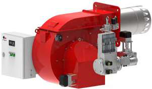
Ambient temperatures in Singapore routinely exceed 30°C, with daily swings of 8–10°C between early morning and peak afternoon heat. This thermal cycling causes differential expansion between electrodes and ceramic insulators, gradually increasing the mechanical stress at mounting points. Vibration from large gas burners (such as the FBR HI-GAS P550/M CE TL industrial gas burner) can amplify this stress. Inspect electrode mounting hardware every 6 months in high-cycling applications.
Field Troubleshooting Decision Tree
Symptom: Hard Start (Ignition requires 2+ attempts)
1. Measure electrode gap → If >4 mm, adjust to specification
2. Clean electrodes with brass brush → Retest
3. Measure spark voltage → If <8 kV, replace ignition transformer
4. Measure spark current → If <15 mA after cleaning, replace electrode assembly
Symptom: Intermittent Flame Detection Lockout During Operation
1. Verify UV detector window cleanliness (applies to UV1p detection cell installations)
2. Measure electrode gap and inspect for deposits
3. If gap is within specification but spark appears weak, test ignition transformer capacity
4. Verify safety relay contact closure (measure voltage drop across Combutech Flame relay CF1 contacts—should be <0.5 V DC at rated current)
Symptom: No Spark / No Ignition Attempt
1. Verify 24 VAC control circuit at the ignition control module input (typical control signal voltage)
2. Measure primary ignition transformer input voltage
3. Measure secondary transformer output voltage → If 0 V, transformer is faulty
4. Test electrode continuity and gap resistance → If open circuit, replace electrode assembly
Conclusion
Electrode gap and spark quality failures represent preventable burner downtime when systematic diagnostic procedures are applied. By establishing baseline measurements, implementing seasonal maintenance protocols tailored to Singapore's climate, and integrating electrode assessment into your flame detection troubleshooting procedures, HVAC contractors can significantly reduce nuisance lockouts and hard-start complaints.
3G Electric's 35+ years of equipment distribution experience in Southeast Asia demonstrates that facilities implementing quarterly electrode inspections and six-month replacement cycles reduce ignition-related service calls by 40–50% compared to reactive maintenance approaches. Partnering with a reliable distributor for quality replacement electrodes and diagnostic equipment ensures your technicians have access to accurate specifications and genuine components.
For specific electrode specifications matching your installed burner equipment, contact the 3G Electric technical support team with your burner model and control system details.