Understanding Burner Control Relays in Combustion Systems
Burners & Combustion systems depend on sophisticated control relays to manage the sequence of events from ignition through sustained flame monitoring. A control relay is an electromechanical or electronic device that monitors multiple inputs—pilot flame presence, main flame confirmation, pressure conditions, and temperature signals—and orchestrates the corresponding outputs to ignition electrodes, fuel solenoids, and air dampers.
Unlike simple on-off switches, modern burner control relays implement multi-stage logic that prevents fuel from reaching the burner without confirmed ignition, protects equipment from flame-out conditions, and ensures rapid shutdown if any safety parameter is violated. For HVAC contractors in Singapore's tropical climate and high-density industrial corridors, understanding relay functionality is essential for system commissioning, troubleshooting, and compliance with local electrical codes.
3G Electric has distributed industrial combustion equipment for over 35 years, working with contractors across Southeast Asia to specify and integrate control systems that meet international safety standards. The selection and installation of the correct control relay directly impacts system reliability, downtime costs, and regulatory compliance.
Flame Detection Methods and Relay Response Logic
Burner control relays employ two primary flame detection technologies: ionization monitoring and ultraviolet (UV) sensing. Each method has distinct advantages and failure modes that affect relay selection.
Ionization Flame Detection:
Ionization detects flame by measuring electrical conductivity across the flame itself. When gas ignites, ions in the flame conduct a small electrical current between electrodes positioned in the combustion chamber. The relay monitors this current continuously; if it drops below a threshold, the relay interprets this as flame loss and initiates shutdown sequences.
Advantages:
- Fast response (milliseconds) to flame loss
- Simple electrode design, low cost
- Effective for natural gas and lighter fuels
Limitations:
- Sensitive to electrode fouling and carbon buildup
- Can be affected by electromagnetic interference in industrial environments
- Less reliable with heavy fuel oils containing conductive ash
The Brahma Relay CM 31 F TW10/TS5 employs ionization flame monitoring with intermittent pilot operation, making it suitable for gas burner applications where rapid pilot ignition and flame confirmation are required. This relay is commonly specified for modular heating systems and industrial process burners operating in the 50–300 kW range.
Ultraviolet (UV) Flame Detection:
UV sensing uses a photocell sensitive to ultraviolet radiation emitted by the flame itself. The relay monitors UV light intensity; sustained UV presence confirms combustion, and its absence triggers shutdown logic.
Advantages:
- Immune to electrode fouling
- Works reliably with oil, gas, and dual-fuel burners
- Not affected by electromagnetic noise
- Better for high-power industrial burners (>300 kW)
Limitations:
- Slightly slower response than ionization (50–100 ms)
- Requires clear line-of-sight to flame
- More expensive than ionization relays
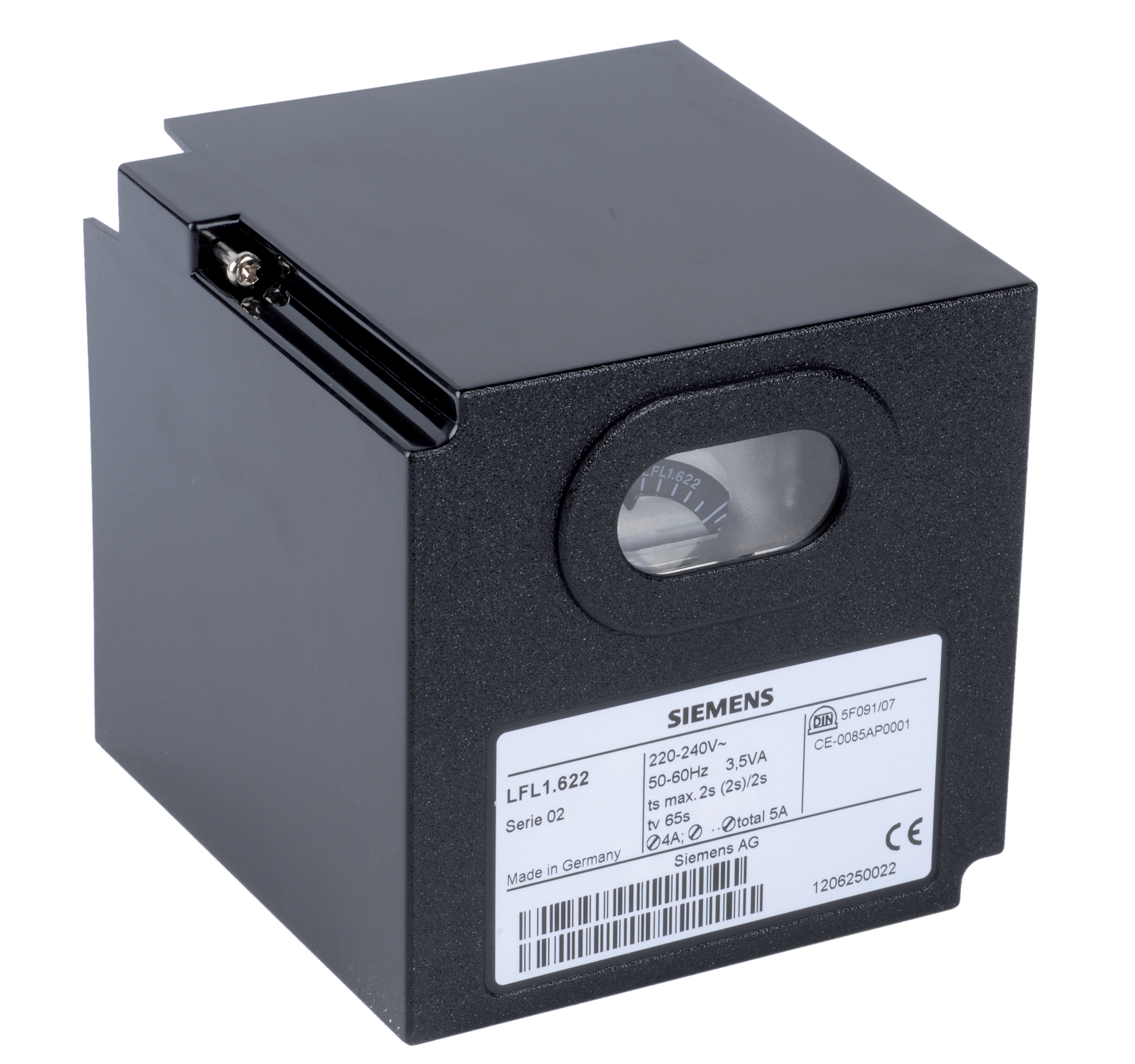
The Siemens Relay LFL 1.622 combines both UV and ionization flame monitoring, offering redundant detection for medium to high-power burners (typically 20–600 kW). This dual-sensing approach is increasingly mandated in Singapore industrial applications where system downtime carries significant financial penalties.
Ignition Sequencing and Pilot vs. Direct Ignition Modes
Burner control relays manage two distinct ignition strategies: direct ignition and pilot-ignition systems. The choice affects energy consumption, response speed, and safety margins.
Direct Ignition:
Direct ignition applies electrical spark directly to the main burner nozzle without a pilot flame. The relay energizes the ignition electrode for a defined period (typically 2–5 seconds), then monitors for main flame detection. If flame is confirmed, the relay maintains fuel flow. If not, it cuts fuel and retries up to a preset number of cycles.
Advantages:
- Faster system startup (5–10 seconds to full heat)
- Lower continuous pilot gas consumption
- Simpler burner design, fewer nozzles
Limitations:
- Requires robust ignition electrode design to withstand repeated spark cycles
- More sensitive to fuel quality and ignition timing
- Higher electrical demand during startup
Pilot ignition uses a small, continuously burning or intermittently reignited pilot flame to ignite the main burner when demand is signaled. The relay first confirms pilot flame, then opens the main fuel valve. The main flame's UV or ionization signature then confirms successful main burner ignition.
Advantages:
- More reliable ignition in adverse conditions (fuel quality variation, moisture)
- Longer ignition electrode lifespan (fewer spark cycles)
- Better for high-power burners where direct ignition spark might be insufficient
Limitations:
- Continuous or frequent pilot operation consumes additional gas
- Slower startup sequence (pilot + main sequence = 15–25 seconds)
- More complex burner assembly and tuning requirements
The Kromschroder Relay BCU 570WC1F1U0K1-E supports both direct ignition and intermittent/continuous pilot ignition modes, compliant with EN 746-2 and EN 676 European safety standards that are widely adopted across Singapore's industrial sector. This flexibility allows contractors to adapt the relay to different burner configurations and customer preference for startup speed vs. fuel economy.
Pressure Monitoring and Safety Interlocks
Burner control relays integrate pressure switches to verify safe operating conditions before and during combustion. Two critical pressure measurements are monitored:
Fuel Pressure:
The relay confirms that fuel pressure is within the designed range (typically 0.5–5 bar for gas burners, 5–20 bar for oil burners) before opening the main fuel solenoid. If fuel pressure drops during operation, the relay cuts ignition and triggers a shutdown alarm.
Air Proving Pressure:
Many burners operate with forced-air supply (fan-powered combustion air). The relay monitors air fan discharge pressure or flow to confirm that adequate oxygen is available before ignition is permitted. This interlock prevents attempting to ignite a burner with blocked air intake or failed combustion fan.
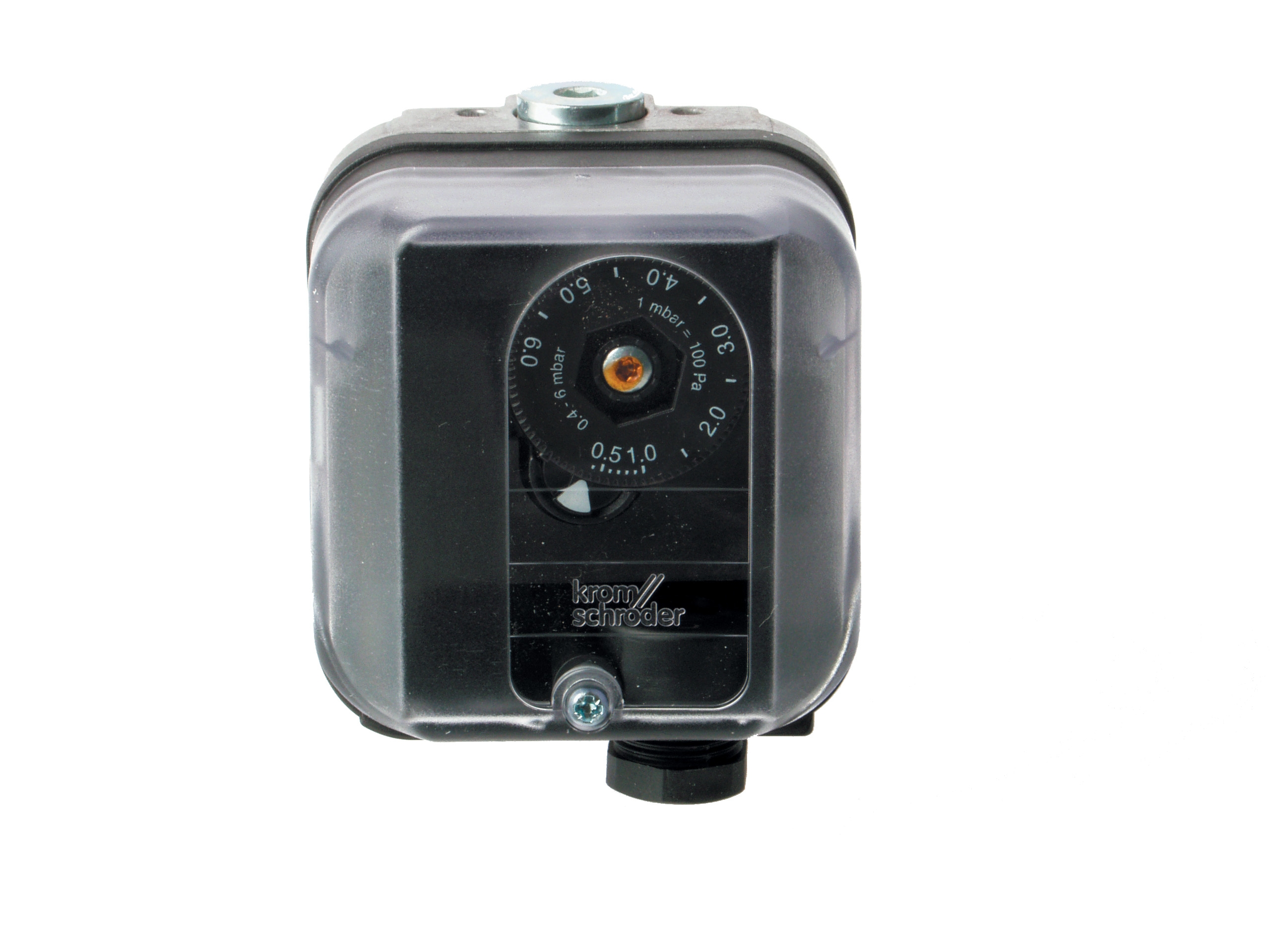
The Kromschroder Pressure Switch DG 50U/6 is a compact differential pressure switch rated SIL 3 (Safety Integrity Level 3) and Performance Level e under EN 13849-1, meeting international functional safety standards. This switch is commonly integrated into relay logic circuits to monitor fuel pressure differentials and trigger shutdown if pressure drops below safe thresholds. In Singapore's hot, humid environment where corrosion and sensor drift are accelerated, SIL 3-rated switches minimize false positives while maintaining robust safety margins.
Relay Selection Matrix for Singapore HVAC Applications
Intermittent Ignition Mode (Small to Medium Burners, 20–150 kW):
Use ionization or UV relays with intermittent pilot ignition. Suitable for modular boilers, unit heaters, and comfort heating systems. The Brahma CM 31 F TW10/TS5 is typical of this category.
Continuous Operation (Medium to High-Power, 150–600 kW):
Specify dual-detection relays (UV + ionization) with continuous or intermittent pilot modes. The Siemens LFL 1.622 fits this application range. Dual detection provides redundancy for critical heating loads such as institutional buildings, data centers, and industrial process systems.
Fuel Flexibility and High Power (300+ kW, Dual-Fuel or Oil):
For burners operating on natural gas, LPG, or fuel oil, UV detection is mandatory due to ionization's poor performance with heavy fuel and conductive ash. Ensure the relay supports both gas and oil nozzle configurations. Pair with SIL 3-rated pressure switches such as the Kromschroder DG 50U/6.
Singapore-Specific Considerations:
- All relays must comply with Singapore Standard SS 638 (Gas Installations) and Code of Practice for Gas Installation issued by EMA (Energy Market Authority)
- Tropical humidity and salt-air corrosion near coastal areas mandate IP 55+ rated control enclosures
- Frequent power interruptions and voltage fluctuations require relays with robust input filtering and low-voltage dropout protection
- Gas approval authority certification (often referenced to EN 746-2) is essential for insurance and regulatory sign-off
Practical Installation and Commissioning
When integrating a burner control relay into a new or retrofit heating system:
1. Verify Electrical Compatibility: Confirm supply voltage (typically 230V or 400V 3-phase in Singapore), frequency (50 Hz), and circuit protection rating. Many relays require 10 A or higher circuit breakers; undersized protection will cause nuisance trips.
2. Test Flame Detection Sensor: Before sealing the burner, manually trigger the ignition electrode and observe pilot flame. Use an ohmmeter to verify electrode insulation (>1 MΩ resistance) and clean any carbon buildup. For UV sensors, check lens clarity and absence of mechanical damage.
3. Calibrate Air and Fuel Pressure Switches: Pressure switches must be set slightly above the minimum safe operating pressure to avoid frequent shutdown, but low enough to catch actual pressure loss. In Singapore's humid environment, allow for sensor drift; recheck calibration after 6 months of operation.
4. Run Commissioning Cycles: Execute at least 5 consecutive ignition-shutdown cycles while monitoring relay response times and flame signal strength. Ignition should occur within 3–5 seconds; shutdown on simulated flame loss should occur within 2 seconds. Document these baseline measurements for future troubleshooting.
5. Install Redundant Safety Cutouts: Beyond the relay itself, install manual fuel shut-off valves and pilot safety valves that require manual reset after shutdown. This provides fail-safe protection if the relay's electronic logic fails.
Supporting System Integration
Modern burner control relays rarely function in isolation. They integrate with broader building management systems (BMS), modulating valve controllers, and remote monitoring platforms. Key integration points include:
- Modulation Signal Input: If the burner operates in a modulating (variable-power) mode, the relay accepts a 0–10 V or 4–20 mA analog signal that adjusts fuel flow without cycling ignition.
- Status and Alarm Outputs: Relays provide digital outputs (24 V dry contact or 0–10 V analog) indicating burner status (running, shutdown, fault code) for transmission to building automation systems.
- Remote Shutdown: Large industrial installations require remote emergency stop (E-stop) capability wired to the relay's de-energize input.
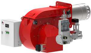
The FBR GAS XP 60/2 CE TC EVO is a two-stage industrial gas burner (116–630 kW) that integrates with modern relay systems via dual-stage solenoid valve control, allowing the relay to stage burner output up or down based on heating demand. This integration minimizes thermal cycling and extends equipment lifespan.
Compliance and Record Keeping
In Singapore, HVAC contractors must maintain detailed commissioning records including:
- Relay model, serial number, and certification documentation
- Pressure switch calibration settings and test dates
- Flame detection response times (measured with oscilloscope or data logger)
- Electrical schematic showing relay integration with fuel solenoids, ignition electrode, and pressure switches
- Maintenance log including annual inspections and any component replacements
These records are typically required for insurance underwriting and regulatory compliance audits. 3G Electric can provide technical documentation and certification copies for all specified components to streamline your compliance filing.