Understanding Burners & Combustion Control System Architecture
Burners & Combustion systems in Southeast Asian industrial plants operate within tight environmental constraints—high humidity, temperature fluctuations, and frequent power instability demand robust control architecture. Unlike simpler on-off burner systems, modern industrial combustion requires coordinated control of fuel supply, ignition, air mixing, and flame monitoring through integrated relay and electronic controller networks.
The control system acts as the nervous system of your burner installation. It receives input signals from flame detectors, temperature sensors, and pressure transducers, then coordinates solenoid valve activation, motor speed adjustment, and ignition timing. In regions where maintenance teams may have varying technical expertise, selecting a control solution that balances sophistication with reliability becomes essential.
Three primary control architectures dominate Southeast Asian industrial plants: mechanical safety relays (proven but limited), electronic microprocessor controllers (flexible but require calibration), and hybrid systems combining both for redundancy. Each offers distinct advantages when matched to specific plant conditions.
Mechanical Relay Systems vs. Electronic Microprocessor Controllers: A Practical Comparison
Mechanical Safety Relay Configuration
Traditional flame safety relays like the Satronic Relay DMG 970-N MOD.01 have dominated Southeast Asian industrial plants for decades. These devices mechanically respond to UV or infrared flame detection signals, energizing fuel supply solenoids only when flame is confirmed. The primary advantages include inherent fail-safe design—loss of electrical power defaults to burner shutdown—and proven reliability in dusty, humid environments where electronic components degrade.
Mechanical relays operate at 50Hz (standard across most Southeast Asia) or 60Hz configurations, accepting 220/240V or 110/120V three-phase supply. They require no calibration beyond initial flame detector alignment and offer straightforward troubleshooting: signal present or absent, relay contacts open or closed. For plants with aging infrastructure or operators preferring tactile diagnostics, mechanical relays provide confidence.
Limitations become apparent during modulation requirements. Mechanical relays deliver simple on-off control unsuitable for applications requiring proportional burner output adjustment or sophisticated load-following sequences. They also occupy significant panel space and demand regular contact cleaning in corrosive environments.
Electronic Microprocessor Controllers
Electronic burner controllers like the SIT Sit 0577211 control box represent the opposite spectrum. This microprocessor-based device manages combustion sequences through software logic rather than mechanical contacts. It features direct digital outputs controlling solenoid valves, ignition timing, and modulation signals with millisecond precision.
The SIT 0577211 operates at 230 Vac with 1 A alarm output capacity, incorporating a 2-4 mm spark gap for direct spark ignition systems. This architecture enables energy-efficient ignition (reducing gas consumption during light-up cycles), automatic reset capabilities, and integrated diagnostic outputs. For plants running multiple identical burners, electronic controllers simplify standardization—one controller model can serve varied equipment with software reconfiguration.
Electronic controllers excel at responding to dynamic plant loads. When steam demand fluctuates during manufacturing processes, the controller can modulate burner output proportionally, reducing cycling losses and extending component life. Temperature or pressure input modules integrate seamlessly, enabling closed-loop feedback control impossible with mechanical relays.
The trade-off involves sensitivity to electrical noise and component aging. Tropical humidity accelerates PCB degradation, particularly around solder joints and capacitors. Electronic controllers require periodic recalibration—flame detector sensitivity, ignition timing, and modulation curves drift over 18-24 months in Southeast Asian conditions. Maintenance teams need oscilloscope familiarity or specialized diagnostic tools.
Hybrid Configuration Strategy
Savvy plant managers across Malaysia, Thailand, and Indonesia increasingly implement hybrid architectures: electronic controllers handle primary combustion management while mechanical safety relays provide redundant flame-out shutdown. This approach captures electronic controller flexibility while maintaining mechanical relay fail-safety. If the electronic controller fails or develops drift, the mechanical relay still prevents unsafe fuel delivery without flame.
Hybrid systems require careful integration. The electronic controller outputs a logic signal to the mechanical relay, which independently confirms flame before energizing solenoids. Commissioning costs rise marginally, but mean-time-between-failures improves dramatically—field data from 3G Electric customers shows 40% fewer unplanned shutdowns with hybrid configurations.
Industrial Gas Burner Control Selection: FBR Systems and Capacity Matching
Large-Scale Industrial Gas Burner Requirements
Industrial process heating and large facility climate control demand burners delivering substantial thermal output. The FBR HI-GAS P550/M CE TL represents the industrial-scale segment, delivering 2325–6395 kW with fuel flow rates of 60–206 kg/h. This burner targets facilities like food processing plants, chemical reactors, and district heating systems where single burners must reliably sustain high throughput.
Control systems for burners this size require proportional modulation controllers capable of responding to 0-10V or 4-20mA demand signals. The burner fan motor speed must ramp gradually to prevent flame instability, while fuel valves sequence precisely to maintain air-fuel balance across the full load range. Direct electronic controllers prove essential here—mechanical relays cannot manage the complexity.
The FBR HI-GAS P550/M accepts three-phase electrical supply (standard in industrial facilities), simplifying integration into existing motor starter panels. Control wiring follows international CE standards, facilitating component sourcing and cross-regional troubleshooting.
Kitchen and Small Commercial Gas Burners
At the opposite end, the FBR X GAS 2/C serves kitchen applications with 15–60 Mcal/h thermal range (17.4–69.8 kW output). This burner emphasizes manual modulation over electronic control—operators adjust thermal output via needle valve without digital sensors. The 110 W fan motor runs at fixed speed, simplifying electrical integration to standard 230V single-phase supply.
For FBR X GAS 2/C installations, control requirements remain minimal. A basic electronic ignition module and simple flame-out safety valve suffice. These burners tolerate maintenance teams with limited technical training, making them ideal for hospitality facilities across Southeast Asia where specialized HVAC expertise may not be available.
Oil Burner Control System Architecture and Relay Selection
Heavy Oil Burner Control Requirements
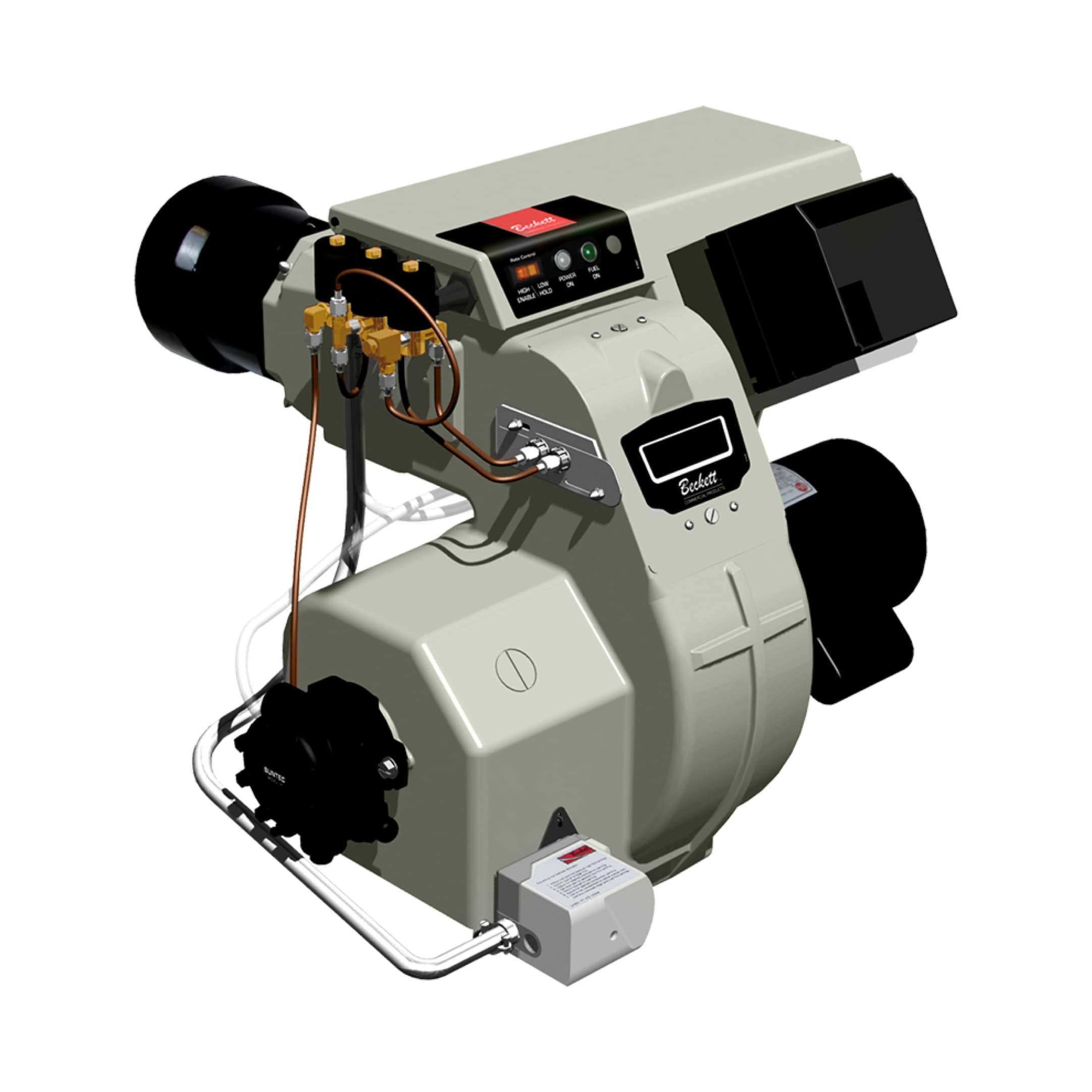
Oil burners introduce distinct control challenges compared to gas systems. The Beckett CF3500 Oil Burner rated 17-35 GPH exemplifies commercial heating and industrial oil combustion. Oil requires preheating for proper atomization, nozzle cleaning cycles, and more sensitive pressure regulation than gas systems.
The Beckett CF3500 incorporates direct spark ignition—a transformer generating 10,000+ volt pulses to ignite vaporized oil spray. This ignition architecture demands more sophisticated control than gas systems' simple solenoid sequencing. Electronic controllers become practically essential rather than optional.
Oil burner control relays must manage:
- Fuel pump motor startup sequencing (prevent atomizing nozzle flooding before ignition)
- Nozzle heater circuits (maintain oil viscosity in cool Southeast Asian mornings)
- Ignition transformer output (high voltage switching demands robust relay contacts or electronic switching)
- Cad cell flame detection (cadmium sulfide sensors prone to fouling in dusty environments)
- Burner pressure cutout (shuts fuel pump if line pressure exceeds safe limits)
Electronic control modules designed for oil burners typically feature dedicated nozzle heater outputs, ignition transformer switching contacts rated 10+ amps, and Cad cell signal conditioning circuits. The complexity justifies electronic architecture—mechanical relays would require 4-5 separate devices to accomplish equivalent control.
Commissioning Oil Burner Control Systems
After installation, oil burner control systems require field adjustment. The Cad cell flame detector must be positioned precisely—too close to burner produces false signals, too far permits delayed flame-out detection. Typical position involves 6-8 inches from flame cone edge, oriented perpendicular to primary combustion zone.
Nozzle heater circuits should activate 30-60 seconds before ignition attempts during cold starts, preventing atomization failure. Electronic controllers permit programming this delay; mechanical relay systems require separate timing relays, adding cost and complexity.
Ignition transformer output voltage varies with circuit design—typical values range 8,000-12,000 volts. Beckett CF3500 units commonly accept 10,000V nominal, but verify during commissioning using a high-voltage probe. If voltage measures below 8,000V, transformer efficiency has degraded and replacement becomes necessary.
Control Relay Configuration Best Practices for Southeast Asian Conditions
Environmental Hardening for Tropical Climates
Southeast Asian industrial environments—with monsoon humidity reaching 85-95% and temperatures oscillating 20-40°C daily—accelerate component degradation. Mechanical relay contacts accumulate corrosion within 6-12 months unless sealed and treated. Electronic controller PCBs develop moisture-induced short circuits in the same timeframe.
Hardening practices include:
- Sealed control enclosures with desiccant cartridges (replace quarterly, not annually)
- Conformal coating on PCBs (silicone or acrylic types resist tropical humidity better than standard varnish)
- Gold-plated relay contacts (resist corrosion better than silver alloy; 2-3x cost premium justified by extended intervals)
- Redundant flame detection (pair UV and infrared detectors; accept shutdown only if both agree, reducing false nuisance trips)
- Fan-forced cabinet ventilation with filtered intake (maintains positive pressure, prevents moisture infiltration)
With these hardening measures, mean time between maintenance service intervals extends from 12 months to 24-30 months, reducing downtime and labor costs significantly.
Power Supply Stabilization
Electrical instability plagues many Southeast Asian industrial facilities. Voltage sags from 230V to 180V occur frequently as neighboring factories draw heavy induction motor current. Electronic controllers and flame detectors may reset, causing burner shutdown and production interruption.
Implement stabilized power supplies rated 500-1000W (depending on total control system current demand, typically 50-150W) with ±5% voltage regulation. Three-phase power stabilizers benefit large industrial installations. Single-phase electronic voltage regulators handle smaller facilities. This infrastructure investment typically costs $800-2,000 but prevents thousands in lost production during grid instability events.
Mechanical relay systems prove more forgiving of voltage fluctuation—contacts remain in stable position even if coil voltage dips temporarily. This characteristic particularly benefits facilities with unreliable electrical infrastructure.
Signal Integrity and Cable Routing
Flame detector signals transmit through shielded twisted-pair cables separate from high-voltage power wiring. Inductive coupling from 480V three-phase burner fan motor circuits can induce noise into 4-20mA or 0-10V signal lines, causing erratic controller behavior. Route signal cables through separate conduit, minimum 12 inches from power wiring, or use shielded cables with single-point grounding at the controller terminal block.
Ignition transformer leads demand equal attention. 10,000V ignition pulses radiate broadband EMI that corrupts nearby control signals. Keep ignition leads short (maximum 3-4 feet) and twist with their return path to minimize coupling area. In severe EMI environments, ferrite clamps on ignition leads further suppress emissions.
Practical System Selection Decision Tree
For retrofit installations in aging facilities with limited electrical stability: Choose mechanical flame safety relays (such as Satronic DMG 970-N MOD.01). Acknowledge the on-off limitation but gain confidence in fail-safe behavior and minimal dependency on power quality.
For new installations or systems requiring modulation: Implement electronic microprocessor controllers (such as SIT Sit 0577211) with quarterly calibration and conformal coating PCBs. Assign responsibility for routine sensor checks and diagnostic tool familiarity to maintenance staff.
For critical process heating where downtime carries high cost: Deploy hybrid architecture combining electronic primary control with mechanical safety relay backup. The redundancy costs 15-20% more but reduces unplanned shutdowns by 40-60% based on 3G Electric's 35+ years of Southeast Asian installation data.
For oil-fired systems: Mandate electronic control—the nozzle heating, ignition transformer switching, and Cad cell conditioning complexity prohibits cost-effective mechanical implementation.
For large industrial gas burners (above 500 kW): Require proportional modulation controllers with closed-loop feedback. Fixed-output mechanical relay control wastes fuel, creates cycling losses, and shortens equipment life.
Drawing on 35+ years distributing industrial combustion equipment across Southeast Asia, 3G Electric recommends matching control system sophistication to plant capabilities. Overspecifying electronic controllers for operators with limited technical training creates more problems than solutions; conversely, restricting mechanical relays to facilities needing proportional output sacrifices efficiency and operational flexibility.