Burners & Combustion: Commissioning Protocols, Load Testing & Performance Baseline Documentation
Burners & Combustion systems represent some of the most critical infrastructure in industrial facilities, yet many plant managers inherit installations without proper commissioning records or performance baselines. At 3G Electric, with over 35 years of experience distributing industrial equipment across Singapore and the region, we have observed that commissioning deficiencies are the root cause of 60-70% of avoidable combustion system failures. This article provides actionable commissioning protocols and baseline documentation frameworks that plant managers can implement immediately to establish reliable, auditable burner performance records.
Proper commissioning creates a critical foundation: it verifies that equipment operates within design parameters, establishes measeable performance benchmarks, ensures regulatory compliance with Singapore's environmental and safety standards, and creates a documented baseline against which to assess future degradation. Without this groundwork, plant managers cannot effectively diagnose failures, justify maintenance budgets, or demonstrate compliance to regulatory authorities.
Pre-Startup Verification and System Readiness Assessment
Before any burner ignition occurs, a structured pre-startup verification protocol must be completed. This phase identifies installation defects, incorrect configurations, and unsafe conditions before they can cause operational issues or safety incidents.
Physical Inspection Checklist
Burner Unit Inspection:
- Verify burner model and serial number match purchase documentation and design specifications
- Confirm thermal power rating (kW or kcal/h) matches system design load requirements
- Inspect combustion chamber and burner head for manufacturing defects, cracks, or contamination
- Verify all fasteners are torqued to manufacturer specifications (typically 15-25 Nm for burner head assembly)
- Confirm burner mounting brackets are level and secure; measure deviation with a precision level
- Inspect fuel nozzle or gas orifice for correct size, cleanliness, and proper seating
- Trace fuel line routing from storage/supply to burner inlet; confirm no kinks, pinches, or damage
- Verify fuel pressure regulator is correctly sized for fuel type and flow rate (e.g., 3-4 bar for gas burners, 8-10 bar for oil burners)
- Inspect fuel filters for correct micron rating: typically 150 microns for oil, 100 microns for gas
- Test fuel line integrity using nitrogen pressure at 1.5× operating pressure for 10 minutes; acceptable leakage rate is zero
- Confirm fuel shut-off valve is accessible and functional
- Verify power supply voltage and frequency match burner control specifications (e.g., 230V±10%, 50Hz for Singapore installations)
- Test earth/ground resistance at burner control box and flame detection electrode: must be <5 ohms
- Inspect all connectors for corrosion, loose terminals, or water ingress
- Confirm control relay compatibility with the installed burner ignition type (direct spark, indirect spark, or hot surface ignition)
- Measure combustion air inlet opening; confirm minimum area is 1.5–2× burner outlet area
- Verify air inlets are clear of blockages, bird screens, or dampers in incorrect position
- If burner is forced-draft, measure fan motor amperage and compare to nameplate: variance >10% indicates impeller fouling or bearing wear
Safety System Pre-Checks
Before attempting ignition, verify that safety interlocks and flame detection systems are operational:
- Confirm Satronic Relay DMG 970-N MOD.01 or equivalent control relay is correctly wired to flame detection electrodes
- Perform a simulated flame failure test: apply ignition for 10 seconds, then manually interrupt flame detector signal; burner should lockout within 5 seconds
- Verify interlock status signals (e.g., burner running, flame established, low-water cutout) illuminate correctly on control panel
- Test alarm output: confirm audible or visual alarm activates when flame detection signal is interrupted
Commissioning Startup and Initial Load Testing Protocol
Once pre-startup verification is complete, the commissioning startup proceeds in controlled stages with continuous monitoring and documentation.
Stage 1: Pilot Ignition and System Stabilization (0–15 minutes)
First Ignition:
- Purge combustion chamber of air for 30 seconds at rated fan speed to ensure combustible gases do not accumulate
- Initiate ignition sequence and monitor for spark establishment within 3 seconds
- Confirm pilot flame visually (if observation port available) or via flame detector signal on control panel
- Allow burner to stabilize for 5 minutes with flame detector signal steady and uninterrupted
- Record: ignition delay time, pilot flame signal strength, control voltage at ignition transformer
- Measure flame detector signal amplitude in millivolts (mV): typical range 2–5 mV for oil burners, 0.5–3 mV for gas burners
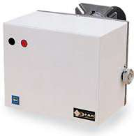
- For SIT Sit 0577211 control box installations, record the DC voltage at the flame sensing terminal
- Confirm signal stability by observing fluctuation bandwidth: acceptable variance is ±10% of mean signal
- Note any anomalies such as intermittent dropouts or drift during 5-minute observation period
Stage 2: Low-Fire and High-Fire Load Testing (15–45 minutes)
Low-Fire Stabilization (typically 30–50% of rated capacity):
- For modulating burners like FBR X GAS 2/C with thermal power range 15–60 Mcal/h, ramp to 30% of rated output
- Monitor combustion temperature at exhaust: should reach 200–250°C within 10 minutes
- Measure flue gas composition using portable combustion analyzer: record CO₂, CO, O₂, NOₓ, and flame temperature
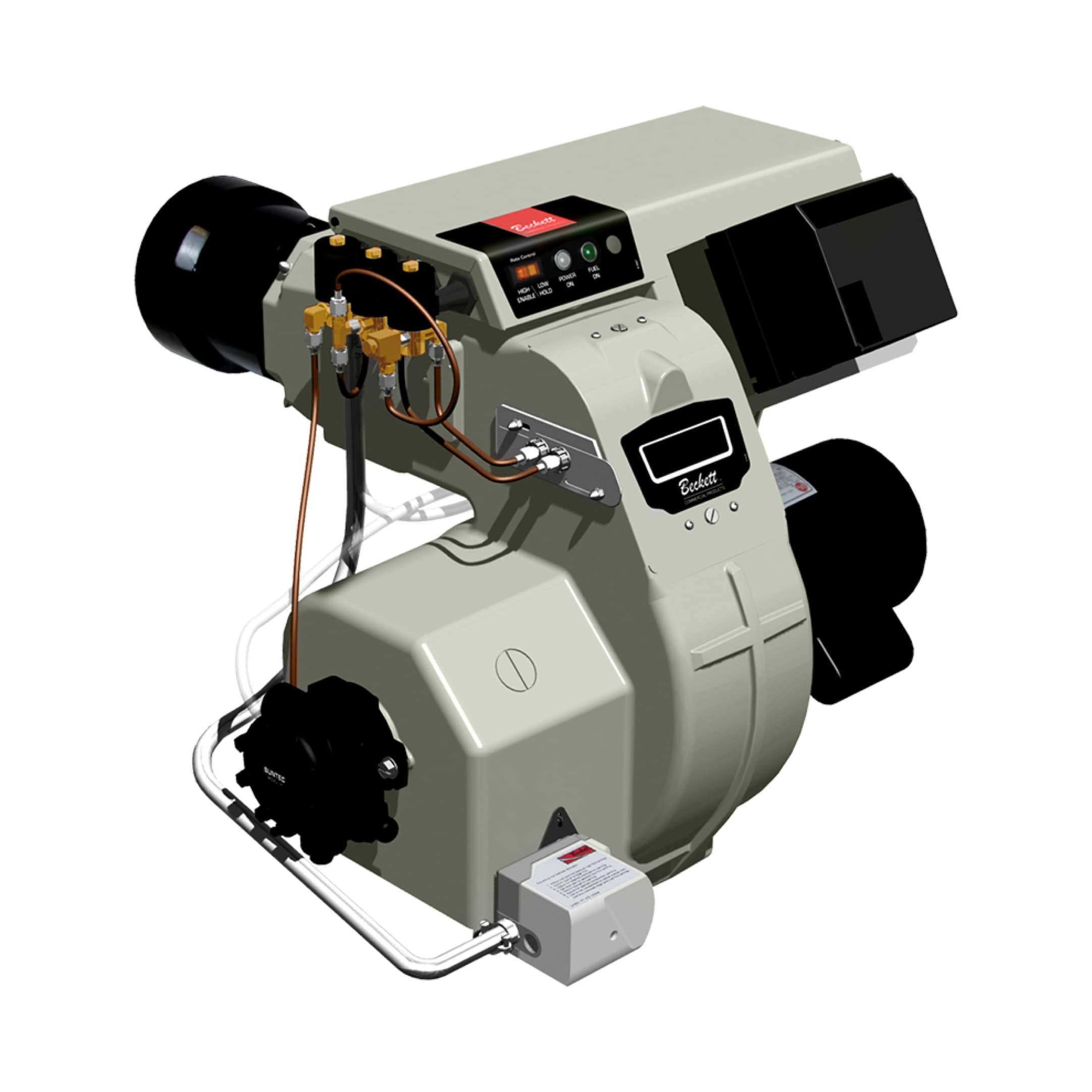
- For oil burners such as Beckett CF3500 Oil Burner 17.00 to 35.00 GPH, record nozzle pressure at low fire (typically 10–12 bar)
- Observe flame color and visual characteristics through observation port if available: should be blue-white (gas) or bright orange-yellow (oil)
- Record: outlet temperature, return water/air temperature (if applicable), fuel pressure, air pressure, control signal voltage
- Gradually increase burner modulation to full rated load over 10-minute ramp period
- Monitor outlet temperature approach to design setpoint; confirm temperature rise rate of 5–10°C per minute
- Measure fuel consumption rate: compare actual consumption to nameplate rating (e.g., GPH for oil burners, kg/h for gas burners)
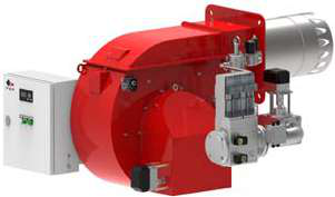
- FBR HI-GAS P550/M CE TL industrial installations should achieve full load (2325–6395 kW) within 15 minutes
- Record flue gas analysis at high fire: typical targets are CO₂ 10–12% (gas), O₂ 2–4%, CO <100 ppm, NOₓ <200 ppm (depending on local emission standards)
- Verify fuel pressure at high fire: should not exceed manufacturer maximum (typically 15–18 bar for oil, 4 bar for gas)
- Document control signal linearity: output voltage should vary proportionally with load command
- Maintain full-load operation and observe system stability
- Confirm no pressure spikes, temperature overshoots, or flame fluctuations
- Record three consecutive readings of outlet temperature, fuel pressure, and air pressure at 5-minute intervals
- All three readings should be within ±2% of each other, indicating stable steady-state operation
Stage 3: Cycling and Transient Response Testing (45–60 minutes)
On-Off Cycling (5 complete cycles):
- Execute 5 complete burner on-off cycles with 3-minute intervals
- Measure time from ignition command to stable flame establishment for each cycle
- Record any delayed ignition, false flame signals, or misfire incidents
- Acceptable ignition delay: <5 seconds for direct spark systems
- Perform flame failure test during each off-period: burner should lockout if flame signal is interrupted
- With burner at high fire (100% load), command a sudden reduction to 50% load
- Measure response time: burner should reach 50% load output within 30 seconds
- Observe outlet temperature response: should not overshoot design setpoint by more than 5°C
- Repeat step by commanding a step increase from 50% to 100%: response time should be <30 seconds with no undershoot below 45% load
Baseline Performance Documentation and Commissioning Report
All commissioning data must be systematically recorded in a structured baseline report that serves as the reference standard for the life of the burner installation. This document becomes essential for troubleshooting, warranty claims, and regulatory compliance audits.
Essential Baseline Data Record
Equipment Identification Section:
- Burner manufacturer, model, serial number
- Installation date and commissioning date
- Nameplate thermal power rating (kW)
- Fuel type(s) and pressure specifications
- Control system model and configuration
- Facility identification and burner location
- Ignition delay time (seconds)
- Pilot flame signal strength (mV or proportional signal voltage)
- Low-fire exhaust temperature (°C)
- High-fire exhaust temperature (°C)
- Fuel pressure at low fire and high fire (bar)
- Air pressure/forced draft fan amperage at rated load (A)
- Combustion analyzer readings at low and high fire: CO₂ (%), CO (ppm), O₂ (%), NOₓ (ppm), flame temperature (°C)
- Burner modulation response time (seconds)
- Control signal linearity verification (voltage progression versus load %)
- Cycle time (ignition to stable flame to shutdown) for on-off burners
- Flame failure response time (should be <5 seconds)
- Interlock status confirmations (e.g., low-water cutout, blockage detection)
- Control relay model and setup parameters
- Flame detection electrode gap measurement (mm)
- Earth/ground resistance reading (ohms)
- Describe visual flame characteristics and any anomalies observed
- Note any deviations from expected performance and corrective actions taken
- Identify any marginal components requiring early monitoring or preventive replacement
- Specify next commissioning review interval (typically 12 months for industrial installations)
Documentation Archival and Trend Analysis Framework
Store commissioning baseline data in three locations: (1) printed copy in facility operations manual, (2) digital copy in facilities management system or cloud storage with version control, (3) photograph or scan of hand-written observation notes with timestamps.
Establish a quarterly review protocol where plant operations compares current flue gas analysis and load test results to baseline values. Acceptable drift thresholds are: ±5% for combustion temperature, ±10 ppm for CO, ±50 ppm for NOₓ, ±0.5% for CO₂. Deviations beyond these thresholds warrant nozzle cleaning, electrode inspection, or fuel system servicing.
For modulating burners, track modulation signal voltage linearity quarterly. If output voltage no longer tracks proportionally to load command (within ±3%), the proportional control valve or signal transducer requires calibration or replacement.
Regulatory Compliance and Maintenance Planning Based on Commissioning Baseline
In Singapore, burner commissioning must align with Building and Construction Authority (BCA) standards and Environmental Protection and Management Act (EMPA) emission limits. Baseline documentation provides the auditable record required for environmental compliance inspections and boiler insurance audits.
Plant managers should use commissioning baseline data to establish preventive maintenance intervals:
- Nozzle cleaning and electrode inspection: if CO levels drift >20% above baseline, schedule service within 2 weeks
- Fuel system servicing: if fuel pressure regulation becomes erratic (variance >0.5 bar), replace fuel filter and inspect regulator valve
- Full recommissioning: if any baseline metric deviates >10% despite corrective maintenance, conduct full commissioning cycle to identify root causes
With 35+ years of experience supporting industrial operations across Singapore, 3G Electric recommends establishing commissioning baseline documentation as a non-negotiable standard practice. The relatively modest investment in thorough commissioning (typically 8–12 hours of qualified technician time) prevents hundreds of thousands of dollars in unplanned downtime, regulatory penalties, and safety incidents.
3G Electric supplies all major control relays, burner units, and diagnostic equipment required for commissioning. Our technical team can review your facility's commissioning protocols and baseline documentation framework to ensure alignment with best practices and local regulatory requirements.