Understanding Burners & Combustion Capacity Fundamentals
Burners & Combustion systems form the thermal engine of industrial facilities, but many plant operations run equipment without confirming actual capacity aligns with installed thermal load. At 3G Electric, our 35+ years distributing global combustion equipment has revealed a critical gap: plants routinely operate burners rated for loads they never encounter, leading to oversized systems, poor turndown ratios, and wasted fuel.
Capacity verification means measuring and documenting what a burner actually delivers under your specific operating conditions—not manufacturer nameplate ratings. A burner labeled 100 GPH for oil or 5000 kW for gas may perform very differently when installed in your piping configuration, with your fuel supply characteristics, and under your facility's seasonal demand patterns.
Load profiling is the counterpart: understanding your facility's true thermal consumption across seasons, production cycles, and operational modes. Without this baseline, retrofit decisions default to worst-case guessing. Plant Managers who implement capacity verification and load profiling reduce commissioning rework by 40-60%, cut energy waste, and position facilities for predictive maintenance strategies.
Load Profiling: Establishing Your Facility's True Thermal Demand
Load profiling begins with data collection across representative operating periods. Capture burner runtime, fuel consumption (gallons/kg per hour), supply pressure, return temperature, and outdoor ambient conditions. For facilities with seasonal variation—industrial boilers, process heating, commercial HVAC—profile over a full 12-month cycle to account for spring/fall turnover efficiency losses.
Key measurements for load profiling:
- Fuel consumption rate: Gallons per hour (oil) or cubic meters per hour (gas). Compare against burner nameplate to identify underutilization or oversizing.
- Temperature delta (ΔT): Difference between hot fluid outlet and inlet. Lower ΔT at constant flowrate signals oversized capacity—the burner modulates down, reducing efficiency.
- Burner on-time percentage: If your burner runs at 30% on-time in winter and 10% in fall/spring, you need modulating (proportional) control, not on-off switching. Fixed-capacity burners cycling heavily degrade nozzles and control components.
- Pressure differential: Monitor fuel supply pressure under load and at idle. Pressure drop signals nozzle wear, filter contamination, or undersized fuel lines—all limit effective capacity delivery.
- Atmospheric conditions: Outdoor temperature, altitude, humidity. Cold climates require higher capacity margins; high-altitude sites need burner de-rating (less oxygen = lower combustion efficiency).
For industrial customers with multiple production shifts, profile each shift separately. A food processing plant running 16-hour shifts has radically different peak loads than one operating 8 hours daily. Load profiling data becomes your retrofit specification baseline—do not proceed to equipment selection without it.
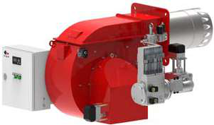
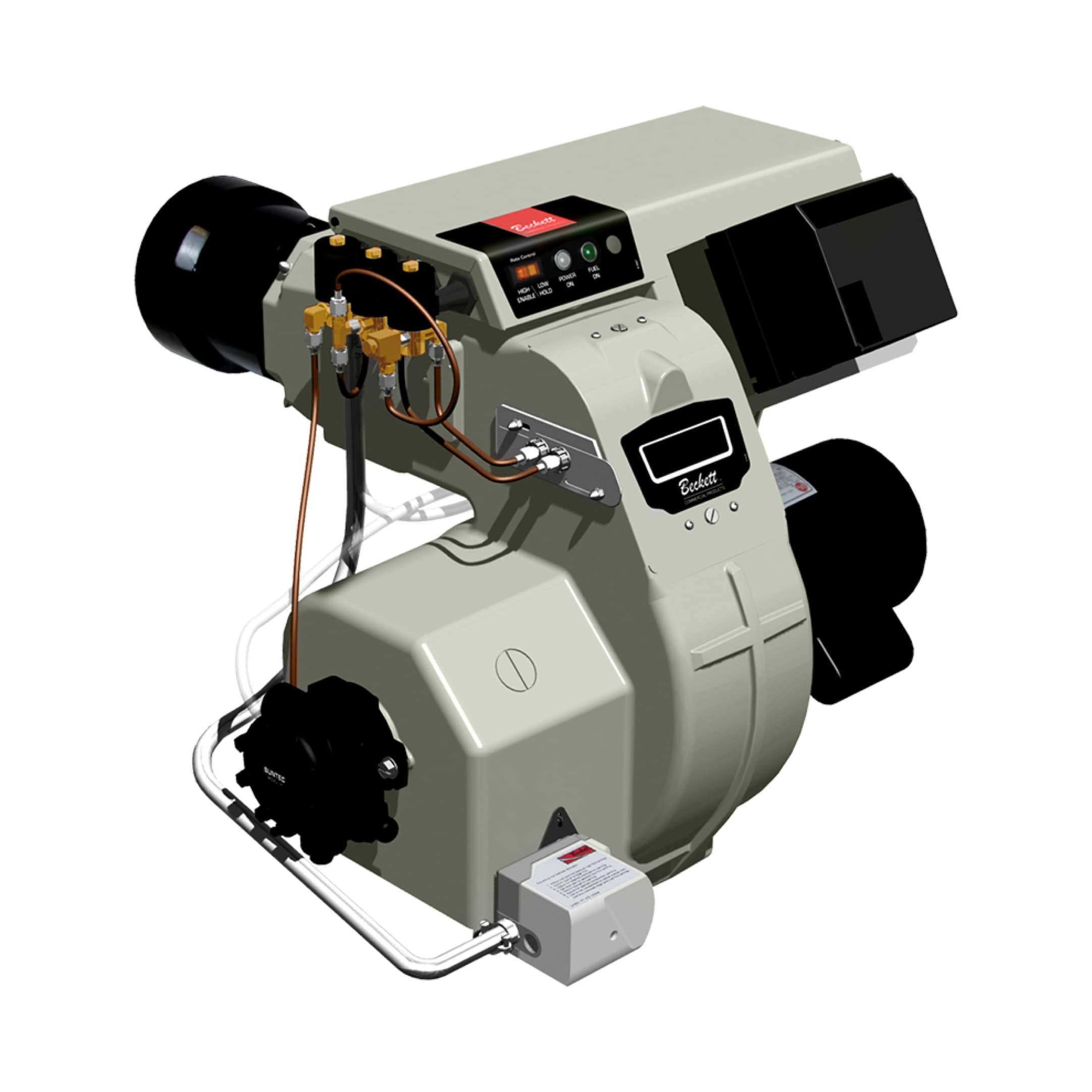
3G Electric's distributed equipment ranges address this variability: The FBR HI-GAS P550/M CE TL industrial gas burner delivers 2325–6395 kW across a broad modulation range, suitable for facilities with 3:1 load variation; the Beckett CF3500 Oil Burner spans 17–35 GPH, giving retrofit flexibility for mid-range commercial heating loads.
Capacity Verification: Testing and Validating Installed Performance
Once load profiles are documented, capacity verification measures what the installed burner actually produces. This differs sharply from commissioning tests focused on safety lockout sequences or ignition reliability.
Capacity verification protocol:
1. Steady-state combustion measurement: Run the burner at full modulation (100% firing rate) for a minimum 30-minute stable period. Measure fuel consumption (using calibrated flow meters or tank-top scales) and thermal output using energy balance formulas.
For boilers: Thermal output (kW) = Fuel mass flow (kg/h) × Fuel calorific value (kJ/kg) × Combustion efficiency ÷ 3600 (conversion factor).
For direct-fire process heating: Measure temperature rise and flowrate of heated medium; output = Mass flowrate × Specific heat × ΔT.
2. Modulation turn-down verification: Command the burner control to 75%, 50%, and 25% firing rates. Confirm fuel consumption tracks proportionally (or within manufacturer tolerance, typically ±10%). Erratic modulation signals control relay malfunction or nozzle inconsistency.
3. Safety margin validation: True installed capacity should be 10-15% above peak calculated load, not 50% above. Oversized capacity indicates retrofit opportunity—replacing an oversized unit with a properly scaled burner reduces part-load cycling, extends component life, and cuts idle gas leakage.
4. Emissions verification: Measure flue gas oxygen (O₂) and carbon monoxide (CO) at full load. Target is 3-4% O₂ (combustion stoichiometry) and CO <50 ppm (depending on local regulations). O₂ >5% or CO >100 ppm indicates incomplete combustion—a capacity leak where fuel energy escapes unburned.
Common capacity verification findings in older installations:
- Undersized nozzles or orifices causing capacity below nameplate (typically 5-15% shortfall).
- Restricted fuel lines or filters reducing supply pressure, limiting actual GPH delivery.
- Corroded burner heads or misaligned electrodes reducing ignition reliability, forcing operators to run on-off cycles rather than modulating control—effective capacity becomes episodic.
- Air supply restrictions (blocked louvers, sealed combustion air ducts) forcing burners to run lean (high O₂, low CO), wasting 5-10% of fuel energy.
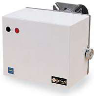
The SIT 0577211 Control Box and Satronic DMG 970-N MOD.01 relay are essential commissioning tools—they log real-time fuel solenoid duty cycles and flame detector signals, providing objective data on whether the burner is modulating smoothly or hunting between on-off states.
Retrofit Planning: Upsizing, Downsizing & System Rebalancing
Retrofit planning bridges verified load and selected capacity. Three retrofit scenarios:
Upsizing: Facility load has grown (expanded production, added process lines, climate change—hotter summers = higher cooling load). Verify that existing fuel supply lines, control voltage, and air ducts can support the larger burner. A 3000 kW burner retrofit into a 2500 kW piping system will experience 20% pressure drop—unacceptable. Budget for fuel line upsizing (typically 25-40% larger diameter) and control relay upgrade (existing relay may not handle higher solenoid current).
Downsizing: Many plants discover load profiling reveals undersized operational demands. A 5000 kW industrial boiler serving a facility with peak loads of 3000 kW runs at 60% modulation minimum, cycling inefficiently. Downsizing to a 3500 kW unit with tight modulation control (proportional solenoid, not on-off) cuts cycling losses by 30-40% and extends nozzle life from 3-4 years to 6+ years. The FBR HI-GAS P550/M CE TL, with its 2325–6395 kW range, allows single-unit retrofit across a 2.7:1 turndown ratio without secondary burners.
System rebalancing: Dual-burner systems (small pilot + large main) are common in older industrial plants. Retrofit planning may consolidate to a single proportional burner (lower maintenance, simpler controls, fewer leak points). Alternatively, if seasonal demand swings from 30% to 120% of average, retrofit planning specifies a dual-burner strategy with proportional modulation on the main burner and intermittent pilot engagement—capturing efficiency across the full range.
Retrofit commissioning checklist:
- Fuel supply confirmation: Measure supply pressure at the new burner inlet under full load. Must be within burner specification (typically 5-10 bar for gas, 3-5 bar for oil). If measured pressure falls short, install a secondary fuel pump before proceeding.
- Control voltage and circuit capacity: New burners may require 230V 3-phase supply; older facilities may only have single-phase. Budget 4-8 weeks for electrical panel upgrade if needed.
- Flame detection compatibility: Match flame detector type to control relay. UV detectors (more common in retrofits) require specific relay modules; ion-rod or photocell detectors need different relay logic. The Satronic DMG 970-N MOD.01 is compatible with IRD 1020 UV and UVD 971 photocell detectors—verify compatibility before ordering.
- Nozzle capacity verification: Nozzle (oil burner) or injector (gas burner) size determines fuel flow. Confirm replacement nozzle matches calculated burner duty; a 17 GPH nozzle in a 35 GPH-rated burner body will starve the flame and reduce capacity by 50%.
- Air intake design review: Oversized burners generate higher air consumption. If existing air louvers or combustion air ducts are undersized, install secondary air supplies to avoid flame impingement and combustion inefficiency.
Retrofit projects typically recover their investment within 18-36 months through fuel savings (5-15% reduction in consumption from better modulation), reduced maintenance (fewer unplanned nozzle cleanings, longer electrode life), and avoided emergency shutdowns from equipment failure.
Commissioning and Performance Validation
Final commissioning after retrofit confirms that capacity, control, and safety operate as designed. This extends beyond startup procedures to validate that your facility now operates within the narrow band of optimal efficiency.
Commissioning sequence:
1. Burner run-in: 24-48 hours of continuous operation (or 8-hour daily cycling for intermittent duty) to establish nozzle flow patterns, control relay response curves, and flame detector sensitivity baseline.
2. Load step test: Increase facility demand in 20% increments (manually modulate the burner, or use thermal load simulation) and confirm burner firing rate tracks proportionally. Measure fuel consumption and flue gas composition at each step.
3. Efficiency curve mapping: Plot fuel consumption (kg/h or GPH) vs. burner modulation command (0-100%). This curve is your performance standard for the next 3-5 years—deviations signal component degradation.
4. Safety function validation: Test lockout sequence (kill fuel solenoid, verify ignition ceases within 3 seconds), test flame detector sensitivity (block light path or remove UV tube; relay must latch within 1-2 seconds), and test pilot / main flame transitions if applicable.
5. Data logging and archival: Export flame detector signal strength, solenoid duty cycle, and control relay runtime logs to establish predictive maintenance baselines. Flame signal trending is the earliest warning of electrode fouling or nozzle wear.
3G Electric's 35-year track record distributing Beckett, Satronic, SIT, and FBR combustion equipment globally gives us direct insight into commissioning best practices. Facilities that document commissioning baselines, maintain accurate load profiles, and schedule annual capacity re-verification operate burners at 5-10% higher efficiency than facilities running reactive maintenance. This translates to 50-150 thousand USD annual fuel savings for mid-size industrial plants.
Plant Managers should treat capacity verification and load profiling as operational governance tools—not one-time commissioning events. Seasonal load shifts, facility expansions, and normal component wear all degrade the match between installed burner capacity and actual thermal demand. A formal annual review (quarterly for facilities with high production variability) ensures your combustion system stays optimized and your retrofit ROI is sustained.