Understanding Burners & Combustion Ignition Architecture
Burners & Combustion ignition systems represent the critical first step in safe equipment startup. Whether operating natural gas, LPG, or oil-fired appliances, the ignition assembly—comprising spark electrodes, gap spacing, high-voltage circuitry, and control logic—must function with precision every time.
Across 35+ years distributing industrial equipment globally, 3G Electric has observed that ignition-related failures are among the most common causes of burner lockouts and service calls. Many maintenance teams treat ignition systems reactively rather than preventively, replacing electrodes only after flame failure occurs. This approach leads to cascading problems: repeat lockouts, nuisance shutdown cycles, and increased wear on control relays.
Modern burner control systems—such as the SIT 0577211 electronic control box—manage ignition timing and spark duration with microprocessor precision. Understanding how these systems interact with the physical ignition electrodes is essential for predictable performance.
Electrode Inspection and Wear Detection Protocols
Visual Inspection Sequence
Electrode condition directly governs ignition reliability. A systematic visual inspection should occur at least quarterly or whenever flame detection issues surface.
Step 1: De-energize and Cool-Down
Always isolate power to the burner control system and allow the combustion chamber to cool for at least 15 minutes before electrode access. Never inspect live electrodes or hot combustion zones.
Step 2: Access and Remove Electrode Assembly
Carefully disconnect the high-voltage lead from the electrode terminal. Note the routing of ignition wiring to ensure correct reinstallation. Remove the electrode assembly using appropriate hand tools—typically a 10 or 12 mm socket depending on mounting bracket design.
Step 3: Document Pre-Removal Condition
Photograph the electrode tip before cleaning. Look for:
- Carbon buildup: Black, crusty deposits indicate incomplete combustion or moisture ingress.
- Pitting or erosion: Crater-like defects on the tip surface signal electrode degradation from repeated spark arcing.
- White or tan deposits: Mineral scale from water contamination or salt-based fuel additives.
- Electrode tip geometry: Sharp, clean tips are healthy; rounded, blunt tips have reduced ignition capability.
Use a soft brass brush or fine emery cloth (220–320 grit) to gently remove surface deposits. Do not use steel wool, as loose fibers can cause tracking (electrical leakage) between electrodes and ground. For stubborn carbon, soak the electrode in acetone for 10–15 minutes before brushing.
Wear Threshold Decision Matrix
After cleaning, measure electrode tip radius and compare to original specifications:
- Radius < 0.5 mm: Electrode shows minimal wear; reinstall and monitor.
- Radius 0.5–1.0 mm: Moderate wear; plan replacement within 6–12 months; monitor spark quality weekly.
- Radius > 1.0 mm or visible pitting/cracking: Replace immediately. Worn electrodes require higher voltage to initiate spark, stressing the control circuit.
Spark Gap Measurement and Calibration
Why Spark Gap Matters
Spark gap—the distance between the electrode tip and ground (usually the combustion chamber wall or a dedicated ground rod)—directly affects ignition voltage requirement and reliability. Too large a gap demands excessive voltage and may fail during cold starts or high-altitude operation. Too small a gap risks flame impingement and carbon accumulation.
The SIT 0577211 control box, for instance, is rated for a 2–4 mm spark gap. Operating outside this range compromises microprocessor regulation of spark timing and duration.
Measurement Procedure
1. Reinstall the electrode assembly with cleaned electrode tip.
2. Use a feeler gauge or dedicated spark gap tool to measure the clearance between electrode tip and the nearest ground surface (combustion chamber wall, quarl, or dedicated ground rod).
3. Record the measurement in your maintenance log. Document date, measured gap (in millimeters), temperature (ambient if cold-start testing), and any observed spark characteristics.
4. Compare to burner nameplate or control box documentation. For most domestic gas appliances and small industrial burners, a 3.0 mm gap is nominal.
Adjustment Techniques
If gap measurement is out of spec:
Gap Too Large (> 4 mm)
- Loosen the electrode mounting bracket by one turn.
- Carefully slide the electrode assembly closer to the ground reference (typically 1–2 mm per adjustment).
- Re-measure and retighten bracket.
- Verify spark visually under low-light conditions; it should appear blue-white and consistent.
- Loosen the bracket and withdraw the electrode slightly.
- Re-measure; small increments prevent over-correction.
- Ensure the electrode tip does not contact the combustion chamber during thermal expansion at operating temperature.
High-Altitude Adjustment
At elevations above 5,000 feet, air density decreases, requiring gap reduction of approximately 0.2–0.3 mm per 1,000 feet of elevation. Consult the appliance nameplate for altitude-specific guidance, or contact the manufacturer.
Ignition Circuit Diagnostics and Control Integration
High-Voltage Output Testing
Once the physical electrode and gap are verified, test the ignition circuit output:
1. Isolate power to the burner control system.
2. Locate the high-voltage output terminal on the control box (typically labeled "HV" or "Spark").
3. Use a high-voltage probe (rated ≥ 10 kV) connected to a multimeter set to the AC voltage scale. A quality ignition tester is preferable; some include spark visualization.
4. Reapply power and initiate a burner start cycle (typically via a thermostat signal or manual test button on the control box).
5. Record peak voltage during the spark phase. Expected range:
- Domestic gas appliances: 6–12 kV
- Industrial burners: 8–15 kV
- Oil burners (like the Beckett CF3500): 10–14 kV with direct spark ignition
If voltage is below range, suspect control board degradation, transformer failure, or loose high-voltage connections. If voltage is above range, verify load impedance (electrode + gap resistance) and consider capacitor aging in the ignition circuit.
Spark Observation Under Load
During a live burner startup (with proper ventilation and safety procedures):
- Spark should appear instantly when the control initiates the ignition sequence.
- Spark color: Blue-white indicates clean combustion; yellow or orange suggests carbon or moisture.
- Spark consistency: Should be steady and uniform across all arcs between electrode and ground. Intermittent sparking indicates electrical tracking or moisture in the combustion chamber.
- Spark duration: Control boxes typically limit spark phase to 5–15 seconds. Verify that spark ceases once flame is detected by the flame sensor (UV cell or ion rod).
Interaction with Control Relays
The Satronic DMG 970-N MOD.01 burner control relay and similar devices manage the handoff from ignition to main fuel valve once flame is confirmed. Ignition failures often stem not from electrode wear but from control relay malfunction:
- Flame detector sensitivity: If the relay's flame detection threshold is set too high, weak sparks (from marginal electrodes) may not ignite fuel consistently.
- Lockout logic: Most safety relays enforce a "prove flame" protocol; if flame is not detected within the ignition window (typically 4–8 seconds), the system locks out and requires manual reset.
- Ignition holdover: Some burners require continuous spark during fuel ignition phase; others terminate spark once main flame is established. Verify the control logic matches the burner design.
Preventive Maintenance Schedule and Record-Keeping
Quarterly Inspection Checklist
- [ ] Visual electrode tip inspection; photograph and log condition.
- [ ] Spark gap measurement with feeler gauge; document in maintenance ledger.
- [ ] High-voltage output test under load; compare to baseline (previous test result).
- [ ] Combustion chamber visual inspection for debris, water droplets, or unusual deposits.
- [ ] Flame detector (UV or ion) lens or rod cleaning; remove dust or condensation.
- [ ] Control box terminal inspection; check for corrosion, loose leads, or burnt insulation.
Annual Deep Service
- [ ] Electrode replacement (preventive) for appliances operating > 1,500 hours/year.
- [ ] Ignition transformer high-voltage winding insulation test (megohm meter at 1 kV DC).
- [ ] Combustion air and fuel line pressure checks; compare to commissioning baseline.
- [ ] Flame detection sensor replacement if sensitivity has drifted > 15% from baseline.
- [ ] Control relay self-check function activation (many modern relays include built-in diagnostics).
Documentation Standards
Maintain a detailed log for each burner:
| Date | Component | Measurement/Observation | Action Taken | Technician | Next Review |
|------|-----------|------------------------|--------------|------------|-------------|
| 2024-01-15 | Electrode | 0.6 mm radius, 3.2 mm gap | Cleaned, monitoring | J. Smith | 2024-04-15 |
| 2024-01-15 | HV Output | 9.8 kV at spark | Within spec | J. Smith | 2024-04-15 |
| 2024-01-15 | Flame Det. | UV cell sensor normal | No action | J. Smith | 2024-07-15 |
This history enables predictive maintenance: trending data often shows gradual voltage drift weeks before catastrophic failure.
Global Industrial Burner Applications and Ignition Variations
Ignition strategies vary significantly by burner type and application:
Small Commercial Gas Appliances
Units like the FBR X GAS 2/C kitchen burner (15–60 Mcal/h, 230 V fan motor) typically use direct spark ignition with a single electrode and simple flame detection (ion rod sensing). Maintenance focus: electrode wear and combustion air flow.
Large Industrial Gas Burners
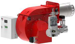
The FBR HI-GAS P550/M (2325–6395 kW, 3-phase supply) employs robust ignition systems with redundant spark electrodes, heated air supply, and sophisticated flame monitoring. Maintenance complexity increases; ignition timing synchronization with fuel valve solenoids is critical.
Oil Burners
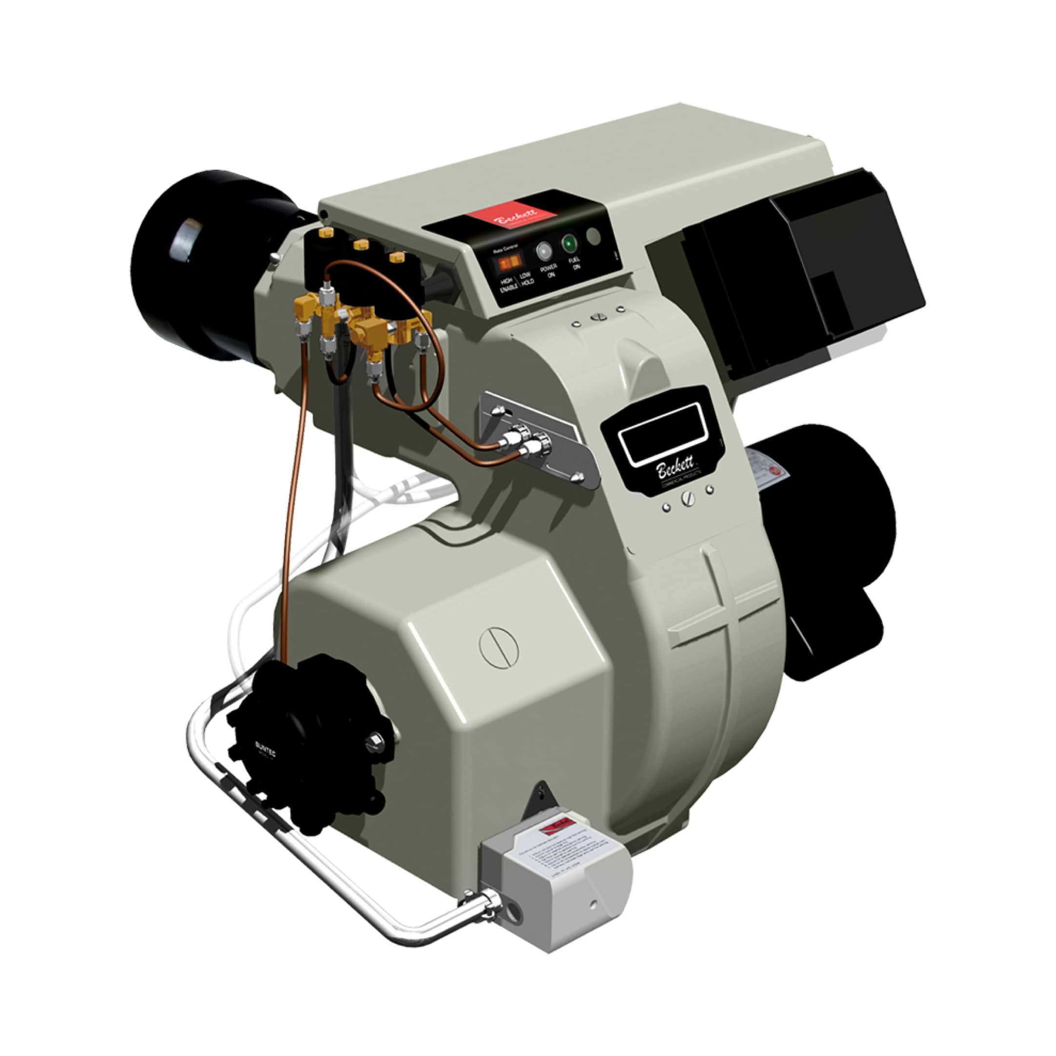
The Beckett CF3500 (17–35 GPH, direct spark ignition) uses an atomizing nozzle and requires precise spark timing relative to fuel atomization. Oil carbon deposits accumulate faster than gas; electrode inspection and combustion chamber cleaning occur every 250–500 operating hours.
Conclusion: Building a Culture of Ignition Reliability
Ignition system failures are largely preventable through disciplined electrode inspection, spark gap verification, and control circuit diagnostics. By adopting quarterly visual protocols and annual deep service, maintenance teams can reduce nuisance lockouts, extend equipment life, and improve facility uptime.
3G Electric's three decades of industrial equipment distribution have taught us that ignition reliability often separates well-maintained facilities from those experiencing chronic downtime. The investment in feeler gauges, high-voltage probes, and systematic record-keeping pays dividends in reduced emergency service calls and safer burner operation across your global fleet.