Understanding Solenoid Valve Function & Failure Modes
Solenoid-operated control valves are the gatekeepers of your fluid systems. Whether managing compressed air in pneumatic networks, controlling water flow in cooling circuits, or directing light oils in automation sequences, these electromagnetic devices must respond instantly and reliably. At 3G Electric, with over 35 years of experience distributing industrial equipment globally, we've seen that solenoid valve failures account for nearly 40% of unplanned maintenance downtime in high-pressure operations.
Unlike mechanical pumps that fail gradually, solenoid valves often fail suddenly. A coil can burn out between one cycle and the next. A stuck plunger can trap your system in a dangerously open or closed state. Understanding the failure modes—electrical, mechanical, and pressure-related—is essential for rapid diagnosis.
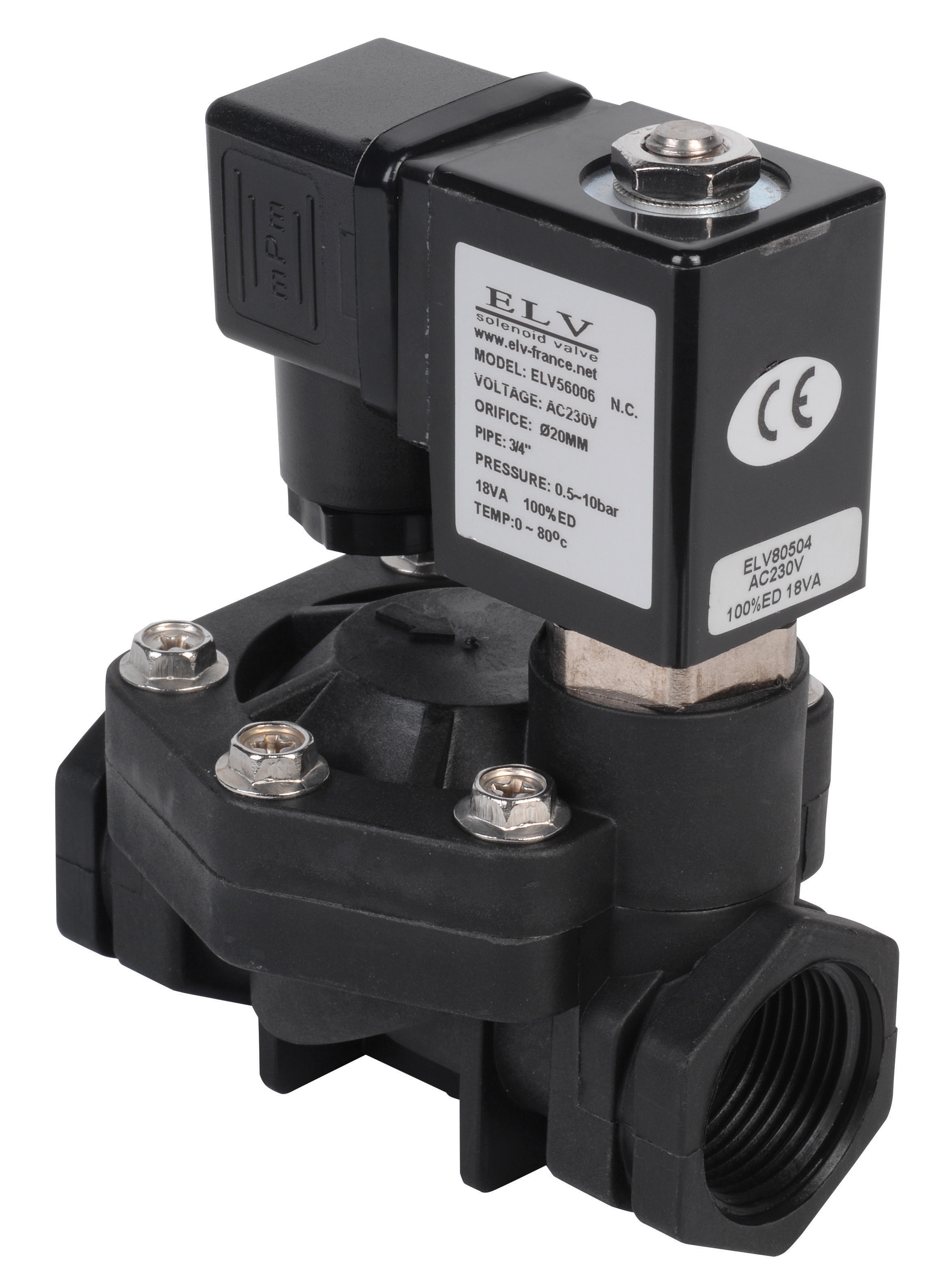
The ELV Plastic Solenoid Valve D.3/4 NF 230V exemplifies modern control technology, handling pressures from 0.5 to 10 bar across compressed air, water, and light oils. However, even robust designs require systematic maintenance and proper troubleshooting when problems emerge. Your maintenance team must recognize the difference between a failed coil, a contaminated valve seat, and an incorrect pressure configuration—each demands a different response.
Electrical Diagnostics: Coil & Circuit Troubleshooting
Coil Failure Recognition
The solenoid coil is an electromagnetic actuator that converts electrical energy into mechanical motion. Coil failures manifest in distinct patterns:
- No voltage at the coil terminals: Check power supply continuity, control relay status, and wiring integrity. Use a multimeter set to AC voltage (for AC coils) or DC voltage (for DC coils). If 230V is specified on the valve nameplate but you measure 0V, the problem is upstream—power supply, circuit breaker, or control circuit.
- Voltage present but no valve response: The coil itself may be open (internal break) or short-circuited. Measure coil resistance with a multimeter. A properly functioning 230V solenoid coil typically measures 1000–3000 ohms. Zero ohms indicates a short; infinite ohms indicates an open circuit. Both require coil replacement.
- Intermittent operation: Partial electrical connection, corroded contacts, or failing coil windings cause erratic behavior. Inspect connector pins for oxidation. Clean contacts with electrical contact cleaner. If intermittent operation persists after cleaning, the coil is degrading and should be replaced before complete failure occurs.
- Coil overheating: Duty cycle violations (continuous energization without rest periods) or sustained high voltage cause coil windings to overheat and burn insulation. Check control circuit logic—solenoid valves require de-energization intervals. If duty cycle is correct, the coil may be undersized for the load.
Proper electrical characterization prevents premature failures. The ELV solenoid valve draws 22 VA at 230V—relatively low power consumption. However, inductive coils create voltage spikes during de-energization, which can damage control circuits and shorten coil life.
- Measure steady-state voltage across the coil during operation. It should match the nameplate rating (±10% tolerance is acceptable).
- Measure current with an ammeter. If current exceeds the rated value by more than 20%, coil windings are partially shorted.
- Use an oscilloscope to observe voltage transients during coil de-energization. Spikes exceeding 2× the supply voltage indicate missing or inadequate snubber diodes (for DC coils) or RC surge suppression networks (for AC coils). Install appropriate surge protection if absent.
Mechanical & Pressure Troubleshooting
Plunger Stiction & Valve Seat Contamination
Mechanical jamming accounts for approximately 30% of field solenoid valve failures. The plunger—a magnetic core that moves inside the coil—must slide freely within tight tolerances (typically 0.1–0.3 mm clearance).
- Symptom: Coil energizes but valve does not open or closes only partially. Measure coil voltage and confirm it reaches specification. If voltage is correct but the valve does not respond, suspect plunger stiction.
- Diagnostic procedure: Listen for the characteristic "click" sound when the coil energizes. Absence of clicking indicates the plunger is stuck. Gently tap the valve body with a soft-faced mallet while energized. If the valve suddenly opens, contamination or varnish buildup is restricting plunger motion.
- Root cause analysis: Particulate contamination in the fluid, mineral deposits from hard water, or degraded lubricant varnish accumulate on the plunger stem and valve seat. This is particularly common in older industrial facilities where fluid maintenance has been deferred.
- Corrective action: Flush the valve with clean fluid compatible with the system. Many maintenance teams install a flush valve (a temporary solenoid with external drain) upstream to force clean fluid through the stuck valve. If flushing fails, the valve requires disassembly, ultrasonic cleaning, and reassembly—or replacement if internal surfaces are pitted.
Solenoid valves are pressure-sensitive devices. Incorrect inlet or outlet pressure creates imbalances that prevent proper opening.
- High inlet pressure blocking opening: If inlet pressure exceeds the solenoid's opening force (the magnetic force generated by coil energization), the valve will not open despite successful coil energization. Typical solenoid opening forces range from 50–150 N, corresponding to pressure differences of 3–8 bar for standard 3/4" valves like the ELV model.
- Outlet pressure exceeding inlet pressure: If outlet pressure is artificially elevated (by downstream backpressure), the valve closes immediately after energization. Check for blocked downstream lines, debris in outlet ports, or incorrect system configuration.
- Air lock in the circuit: Trapped air creates compressibility that prevents smooth valve operation and causes sluggish response. Bleed air from high points in the system using vent valves.
Preventive Maintenance & System Integration
Maintenance Intervals & Fluid Management
Solenoid valve longevity depends critically on fluid cleanliness. Industrial fluids—whether compressed air, water, or hydraulic oil—accumulate particulate matter, moisture, and chemical degradation products.
- Air systems: Install coalescent filters (removes water and oil vapor) and particulate filters (5–10 micron) immediately upstream of solenoid valves. Replace filter elements every 6–12 months, or more frequently in high-humidity environments. Desiccant dryers extend maintenance intervals by removing bulk moisture before it reaches valves.
- Water systems: Hard water deposits are the primary cause of solenoid valve failure in water-cooled industrial processes. Install water softeners or treatment systems. Flush lines quarterly to prevent mineral accumulation on plunger stems.
- Oil systems: Hydraulic fluids degrade over time, forming sludge and varnish. Monitor fluid cleanliness with ISO particle counts. When particle counts exceed ISO 18/16/13, replace or filter the fluid. For high-pressure pump systems like the Pratissoli KF30 (106 L/min, 200 bar) or Pratissoli SN7045 L (45 L/min, 210 bar), maintain fluid cleanliness to protect both pump components and downstream solenoid controls.
Electrical transients from solenoid coil de-energization create voltage spikes that degrade control electronics and shorten coil life.
- For AC solenoid coils, install RC (resistor-capacitor) surge suppression networks across the coil terminals. Typical values: 1 kΩ resistor in series with 0.1 µF capacitor, connected across the coil.
- For DC solenoid coils, install a freewheeling diode (1N4007 or equivalent) across the coil in reverse bias. This diode clamps the inductive voltage spike to approximately 0.7 V above the supply voltage, protecting downstream transistors and PLCs.
- Ensure all solenoid valve installations include a surge-protected relay or solid-state switch to isolate the delicate coil from high-current switching events.
In systems incorporating high-pressure pumps—such as the Interpump PUMP W2035 L ATEX (35 L/min, 200 bar, 13.23 kW, ATEX-rated) for hazardous environments or the Interpump GEARBOX RS500 transmission system—solenoid valve selection and maintenance are critical.
- Solenoid valves must be rated for the full system pressure. A valve rated for 10 bar cannot safely be used in a 200 bar pump circuit; catastrophic failure will result.
- Install pressure relief valves in parallel with critical solenoid control circuits. This prevents pressure spikes during rapid solenoid closure from damaging the valve.
- For ATEX-compliant hazardous-environment applications (like the W2035 L ATEX), select solenoid valves with matching ATEX certification. Non-certified valves void equipment certification and create safety liabilities.
- Maintain adequate spacing between solenoid coils and fluid lines. Heat dissipation is critical—coils rated for 22 VA (like the ELV model) can fail rapidly if surrounded by high-temperature hydraulic fluid without thermal isolation.
Maintenance teams often inherit systems without complete documentation. Establish a baseline:
- Record the nameplate data (voltage, current, pressure rating, flow capacity, manufacturer, model, serial number) for every solenoid valve in your facility.
- Track failure history: date, symptoms, root cause, repair method, replacement part used. This historical record identifies systemic issues (e.g., chronic hard water problems, inadequate filtration).
- Create a preventive maintenance calendar aligned with manufacturer recommendations and your facility's duty cycle. Seasonal variations—increased cooling demand in summer, increased heating in winter—may necessitate more frequent checks during peak periods.
- Store spare solenoid coils and repair kits at your facility, matched to critical applications. Emergency downtime often exceeds parts lead time; keeping 1–2 spare coils for each critical valve model enables same-day repairs.
Common Troubleshooting Scenarios
Scenario 1: Intermittent Valve Opening
- Observations: Valve opens inconsistently; sometimes energization produces no response; sometimes there is a 2–3 second delay before opening.
- Root cause analysis: Suspect coil degradation (partial short), electrical contact resistance, or early plunger stiction.
- Immediate test: Measure coil resistance. If resistance is below specification, replace the coil immediately. If resistance is normal, measure voltage and listen for coil "click." Absence of click indicates failing coil or power supply.
- Long-term fix: Flush the valve and replace if stiction persists after flushing. Add upstream filtration to prevent recurrence.
- Observations: De-energizing the solenoid does not return the valve to its resting position; manual intervention (tapping the valve) sometimes closes it.
- Root cause analysis: Plunger is sticking in the open position, typically caused by contamination or pressure imbalance (outlet pressure exceeding inlet pressure).
- Immediate test: Check outlet pressure. If outlet pressure is elevated due to downstream backpressure, install a proportional relief valve or check the downstream circuit for blockages.
- Long-term fix: Flush the valve and replace if necessary. Install adequate filtration upstream. For critical applications, consider a dual-solenoid valve with assisted spring return for faster, more reliable closure.
- Observations: Coil operates normally for weeks or months, then suddenly fails; replacement coils fail within the same timeframe.
- Root cause analysis: Chronic voltage elevation, incorrect duty cycle, inadequate thermal management, or contamination causing elevated motor current and heat.
- Immediate test: Measure supply voltage continuously over a 24-hour period using a data logger. Voltage variation beyond ±10% indicates a power quality issue. Check system duty cycle—if the solenoid is energized for hours without rest, overheating is inevitable.
- Long-term fix: Install voltage stabilization (if voltage sags are the issue). Reprogram control logic to include de-energization periods. Add thermal isolation or cooling if the valve is mounted near hot hydraulic fluid. Consider switching to a DC solenoid with inherent lower coil temperature rise if AC is not mandatory.
Key Takeaways for Maintenance Teams
Solenoid valve troubleshooting requires simultaneous investigation of three domains: electrical (coil, contacts, voltage), mechanical (plunger freedom, valve seat condition), and pressure-related (inlet/outlet balance, system configuration). By systematically diagnosing each domain, you avoid the common mistake of replacing a solenoid coil when the actual problem is downstream backpressure or upstream contamination.
With 35+ years of distributing industrial equipment globally, 3G Electric understands that solenoid valve reliability underpins the entire fluid system. Investing in proper filtration, electrical protection, and preventive maintenance yields orders-of-magnitude improvement in mean time between failures (MTBF) and dramatically reduces emergency repair costs. Your maintenance team's proactive approach to solenoid valve care protects not only your pumps—like the Pratissoli KF30 and SN7045 L—but also the critical processes those pumps serve.