Understanding Solenoid Valve Failures in Industrial Operations
Solenoid valves operate at the intersection of electrical and hydraulic systems, making them uniquely vulnerable to multiple failure modes. As a distributor with 35+ years of experience supplying industrial equipment across Asia-Pacific, 3G Electric has observed that most solenoid valve problems stem from five core issues: coil burnout, stuck plungers, pressure seal degradation, electrical supply inconsistencies, and contamination in fluid pathways.
Plant managers in Singapore often encounter solenoid valve failures during peak production periods—precisely when downtime costs are highest. Understanding the diagnostic sequence will help your maintenance team address problems systematically rather than through costly trial-and-error replacement cycles.
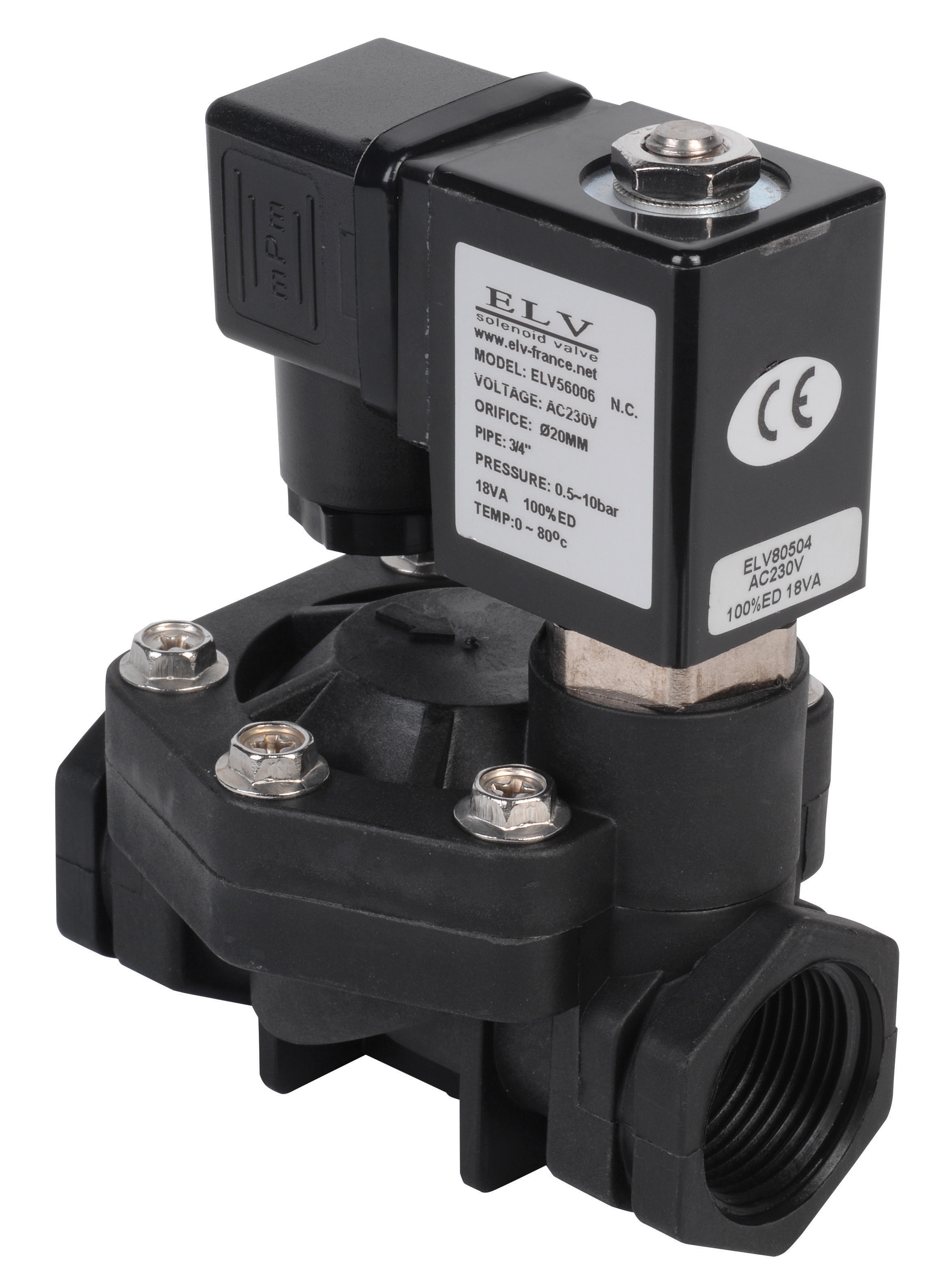
The ELV Plastic solenoid valve D.3/4 NF 230V is a common control component in compressed air and light fluid applications across local manufacturing plants. Its 230V coil and compact plastic body make it susceptible to specific failure patterns that differ from larger industrial solenoid valves used in high-pressure pump systems.
Electrical Coil Diagnosis & Troubleshooting
The solenoid coil is the weakest component in any solenoid valve system. It converts electrical energy into magnetic force, and when it fails, the entire valve becomes inoperable regardless of downstream pressure conditions.
Identifying Coil Failure Symptoms:
- Valve does not respond to electrical signal despite correct 230V supply
- Audible clicking at solenoid when power applied, but plunger does not move
- Intermittent valve actuation (works occasionally, then fails)
- Burning smell or visible scorch marks on coil housing
- Soft resistance measurement with multimeter (below 5 ohms for typical 230V coils)
First, isolate the solenoid valve circuit and measure voltage at the coil terminals using a calibrated multimeter. Confirm you have 230V ±10% (207-253V acceptable for Singapore's electrical standards). Many "solenoid failures" are actually supply voltage problems caused by overloaded circuits, loose terminals, or faulty control relays.
If voltage is present and correct, remove the solenoid coil assembly (typically held by two bolts). Measure coil resistance using an analog or digital multimeter set to ohms. Compare the reading to the coil's rated impedance. A reading near zero ohms indicates internal short-circuit failure. A reading showing infinite resistance (no continuity) indicates an open-circuit break.
Coil burnout accelerates when:
- Valve is held in energized position continuously without designed duty cycle
- Ambient temperature exceeds 60°C without proper thermal management
- Voltage surges occur during pump start-up or motor switching
- Coil housing is exposed to water or oil mist contamination
If coil replacement is required, always source OEM-compatible parts. The ELV 230V solenoid coil is engineered with specific impedance characteristics; non-compatible coils may draw excessive current and fail prematurely.
Plunger Stiction & Seal Degradation Issues
Beyond electrical failures, solenoid valve plungers frequently become stuck due to mineral buildup, oil sludge, or seal degradation. This is especially common in Singapore's humid environment where moisture ingress accelerates corrosion and seal deterioration.
Recognizing Plunger Stiction:
- Solenoid coil energizes (you hear clicking), but valve does not switch
- Manual actuation (pressing on solenoid armature) briefly releases the valve, then it sticks again
- Irregular flow rates even when valve electrically activates
- Grinding or binding sensation when manually operating the plunger
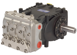
Plunger stiction develops when fluid contamination deposits on the ceramic or metal plunger rod. High-pressure pump systems like the Pratissoli SN7045 L delivering 210 bar create extreme stress on seals. When downstream solenoid valve seals age, microscopic wear particles and oxidized fluid residue accumulate on plunger surfaces.
In compressed air applications using the ELV plastic solenoid valve, stiction often results from moisture condensation inside the valve body. Without proper air dryer maintenance upstream, water droplets create micro-corrosion on the plunger rod, preventing smooth travel.
Maintenance & Service Recovery Procedure:
1. De-energize the solenoid completely and depressurize the system
2. Remove the solenoid coil assembly to expose the plunger rod
3. Apply penetrating oil (light machine oil or WD-40 equivalent) around the plunger rod and allow 30 minutes for absorption
4. Gently tap the coil body with a rubber mallet to vibrate the plunger
5. Manually push and pull the plunger rod 20-30 times with steady pressure
6. If plunger moves freely, flush the internal cavity with clean solvent and allow complete air drying
7. Reinstall the coil and test electrical operation before restoring system pressure
If the plunger remains stuck after oil treatment and mechanical agitation, internal seal damage or corrosion has progressed beyond recovery. Replacement is required. Preventive measures include:
- Installing a 3-micron filter on the inlet side of all solenoid valves
- Maintaining fluid change intervals appropriate for your system pressure and duty cycle
- Using coil protectors or moisture barriers in humid environments
- Implementing monthly manual solenoid actuation tests to detect early stiction
System Pressure Effects & Seal Failure Management
Solenoid valve performance degrades when system pressure fluctuates beyond designed operating ranges. The ELV solenoid valve operates between 0.5 and 10 bar, making it unsuitable for direct integration into high-pressure pump discharge lines from equipment like the Interpump PUMP W2035 L ATEX delivering 200 bar.
Pressure-Related Failure Patterns:
- Solenoid valve leaks internally (downstream port shows upstream fluid)
- Valve sticks in closed position; requires pressure release to open
- Abnormal seal wear detected during teardown inspection
- Erratic valve switching when system pressure approaches rated maximum
When solenoid valves are exposed to pressures exceeding their rated capacity, seals experience uneven compression and extrusion. Over time, seal material permanently deforms. Even after pressure returns to normal operating range, the seal cannot re-establish proper contact with the spool, causing internal leakage.
For high-pressure applications involving the Pratissoli KF30 pump (200 bar operating pressure), solenoid valves must be rated for at least 250 bar minimum pressure. Using a 10-bar rated solenoid valve in such a system guarantees rapid seal failure within days.
Implementing Proper Pressure Control:
1. Install a pressure relief valve immediately downstream of the pump discharge
2. Set relief pressure 10% above maximum required system pressure
3. Use a pilot-operated solenoid valve for high-pressure applications (rated ≥250 bar)
4. Monitor system pressure daily using a calibrated pressure gauge; record readings in maintenance logs
5. Establish quarterly pressure audits to detect creeping pressure increases caused by relief valve drift
When replacing solenoid valve seals, always inspect the spool bore for scoring or corrosion. If the bore shows visible wear patterns, the entire valve body must be replaced—seal replacement alone will not restore function.
Preventive Maintenance & Service Schedule for Singapore Operations
Effective Maintenance & Service prevents the emergency failures that disrupt production. Based on 35+ years of distributor experience across tropical and humid climates like Singapore's, plant managers should implement tiered preventive protocols.
Monthly Inspections (Plant Manager or Lead Technician):
- Visual inspection for oil weeping or moisture on solenoid coil housing
- Listen for audible clicking when solenoid energizes under load
- Manually actuate solenoid valves (with system depressurized) to confirm plunger movement
- Check voltage supply at solenoid terminals using multimeter
- Record any temperature changes or unusual sounds
- Measure solenoid coil resistance and compare to baseline readings
- Inspect solenoid coil for corrosion, moisture, or thermal damage
- Test valve response time using pressure gauge observation (should switch within 500 milliseconds)
- Clean moisture trap on compressed air inlet if applicable
- Replace air filter element upstream of solenoid valve
- Complete solenoid valve disassembly and cleaning
- Seal and spool inspection; replace all seals if any wear detected
- Bore inspection for scoring; replace body if damage found
- Coil electrical testing (megohm resistance check for insulation integrity)
- System flush and fluid replacement if contamination detected
For critical applications using the ELV solenoid valve in process automation, implement dual solenoid redundancy with automatic switchover logic. This ensures production continuity if primary solenoid fails unexpectedly.
Maintain detailed Maintenance & Service logs recording:
- Date and time of each inspection
- Solenoid model, location, and serial number
- Voltage and resistance measurements
- Any issues detected and corrective actions taken
- Seal replacement dates and fluid change records
- Pressure readings at solenoid inlet and outlet
These records build a historical baseline, allowing your team to predict failures before they occur. Trending increasing coil resistance or rising system pressure typically precedes catastrophic solenoid failure by 2-4 weeks, providing advance warning for planned maintenance windows.
Integrating Solenoid Valve Diagnostics Into System Design
When specifying solenoid valves for new systems or retrofit projects, plant managers should collaborate with equipment suppliers to ensure proper integration. 3G Electric's 35+ years of experience includes helping Singapore manufacturers select compatible components for complex fluid systems.
For applications involving the Interpump GEARBOX RS500 transmission integrated with pump systems, solenoid valve control circuits must account for pressure spikes during clutch engagement. These transient pressure surges can exceed steady-state pressure by 50%, prematurely aging solenoid valve seals.
Proper system design includes:
- Accumulator installation to dampen pressure spikes
- Pilot-operated solenoid valves with internal pressure balancing
- Electronic pressure monitoring with alarm setpoints
- Proportional solenoid valves (rather than on-off) for smooth flow modulation
When troubleshooting solenoid valve problems in existing systems, always ask: "Is this a solenoid valve failure, or does the solenoid valve reveal a system design issue?" Frequently, repeated solenoid valve failures indicate upstream pressure problems, fluid contamination, or thermal stress that will continue degrading replacement valves unless root causes are addressed.
Working with a distributor experienced in your industry and regional operating conditions—such as 3G Electric's presence across Singapore and Asia-Pacific—accelerates proper diagnostics and prevents costly replacement cycles.