Introduction: Pumps & Compressors in Hazardous Environments
Pumps & Compressors operating in hazardous classified areas demand specialized engineering and compliance verification that extends beyond standard industrial equipment selection. Whether your facility handles flammable gases, explosive dust atmospheres, or volatile chemical processes, equipment certification and configuration become mission-critical factors in preventing catastrophic incidents.
3G Electric has supplied industrial equipment globally for over 35 years, working with facilities across petrochemical, mining, pharmaceutical, and chemical processing sectors. Our experience shows that equipment failures in hazardous zones often stem not from inherent product defects, but from incorrect specification, improper configuration, or inadequate compliance verification during procurement.
This guide addresses the technical decision-making process for selecting Pumps & Compressors rated for hazardous area deployment, ensuring your facility meets regulatory requirements while maintaining operational reliability.
Section 1: Understanding Hazardous Area Classification and ATEX Requirements
Hazardous Zone Categories and Equipment Groups
Before selecting any Pumps & Compressors, you must establish your facility's hazardous zone classification. The ATEX directive (2014/34/EU) categorizes equipment into:
- Group I Equipment: Mining operations with firedamp (methane) presence
- Group II Equipment: Surface industries with flammable gases, vapors, or mists
- Group III Equipment: Dust-prone environments (grain facilities, metal processing, chemical manufacturing)
Within each group, equipment is further classified by category (1, 2, or 3), reflecting the frequency and duration of hazardous atmosphere presence. A Category 1 pump operates in Zone 0 (continuous presence), while Category 2 equipment functions in Zone 1 (occasional presence), and Category 3 serves Zone 2 (rare/brief presence).
ATEX Certification Marking
Compliant equipment displays the ATEX marking: II 2G Ex db IIB T4 Gb
This designation breaks down as:
- II: Group II (surface industry)
- 2G: Category 2, Gas equipment
- Ex db: Equipment protection type (flameproof enclosure)
- IIB: Gas group (includes propane, ethylene)
- T4: Temperature class (surface temperature limited to 135°C maximum)
- Gb: Level of equipment integrity
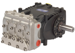
The Interpump PUMP W2035 L ATEX exemplifies proper ATEX compliance. Rated at 35 L/min at 200 bar with 13.23 kW power output, this pump specifically addresses high-pressure applications in classified environments. Its ATEX certification confirms independent testing against flammability and explosion containment standards.
Section 2: Matching Flow Rate, Pressure, and Power Specifications to Hazardous Applications
Flow Rate Selection for Hazardous Process Requirements
Flow rate (L/min or GPM) must align with your process requirements while accounting for system losses and safety margins. Industrial professionals commonly select equipment with 20-30% oversizing to accommodate:
- Viscosity changes due to temperature fluctuation
- Pressure losses through hoses, filters, and manifolds
- Future production capacity increases
For hazardous chemical transfer operations, the Pratissoli SN7045 L pump delivers 45 L/min at 210 bar pressure with an 18.4 kW motor running at 1450 rpm. This specification suits medium-scale transfer systems in petrochemical facilities where consistent flow stability prevents pressure spikes that could trigger safety systems.
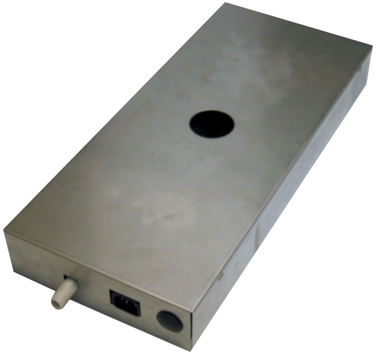
Smaller hazardous operations—such as condensate management in enclosed chemical processing HVAC systems—benefit from the Clima Concept condensate pump with 5-liter reservoir, rated for 110 L/hr continuous flow with 30-meter pumping head. This unit's integrated reservoir and overload protection prevent system flooding in confined hazardous spaces.
Pressure Rating Validation
Pressure specifications must exceed peak system demand plus safety margin. When specifying equipment, apply the formula:
Equipment Rated Pressure = (Peak System Pressure × 1.3) + Safety Buffer
For example, a system requiring 150 bar peak demand needs equipment rated minimum 195-210 bar. The Pratissoli KF30 pump (106 L/min, 200 bar, 40 kW) matches applications requiring moderate flow with robust pressure handling, suitable for multi-stage compression or high-pressure fluid conditioning in hazardous refineries.
Motor Power and Thermal Management
In hazardous areas, motor thermal output directly affects ambient temperature—a critical safety factor. Larger motor power generates more heat, potentially creating ignition hazards in classified zones.
The Interpump WW90 L pump with integrated valve operates at only 1.47 kW, delivering 8 L/min at 90 bar from a compact 177 mm length. This low thermal footprint makes it ideal for tight hazardous enclosures where ventilation is restricted. The integrated valve eliminates external manifold connections, reducing leak points in explosive atmospheres.
High-power equipment like the Pratissoli KF30 (40 kW) requires dedicated thermal monitoring and ventilation planning in hazardous installations to prevent surface temperature limits from being exceeded.
Section 3: Configuration, Integration, and Compliance Documentation for Hazardous Deployments
System Design and Material Compatibility
Hazardous area pump systems demand:
- Piping Material: Stainless steel or copper tubing eliminates galvanic corrosion risk in flammable environments. Avoid black iron pipe, which corrodes unpredictably and creates ignition sources.
- Hose Selection: ATEX-certified hoses rated for the application's pressure and temperature. Standard industrial hoses do not guarantee spark-free performance under failure conditions.
- Relief Valve Configuration: Pressure relief must prevent overpressure conditions that could rupture hoses and release flammable contents.
- Filtration Staging: Pre-pump and post-pump filters maintain fluid cleanliness, essential for preventing internal leakage and pressure losses in small clearance pumps like the WW90 L.
Installation Layout and Spacing Requirements
Equipment spacing in hazardous areas follows ATEX guidance:
- Maintain minimum 1 meter clearance between pump discharge and combustible materials
- Position pressure gauges outside classified zones when possible; if internal placement required, use snubbers to dampen pressure pulsations
- Install secondary containment (drip pans) under all pump connections to capture leakage before vapor concentrations reach LEL (Lower Explosive Limit)
- Provide mechanical anchoring to prevent vibration-induced movement that stresses hoses and connections
For compact hazardous spaces, the WW90 L's 177 mm length and 8 L/min output allow installation in confined equipment cabinets with minimal clearance, reducing footprint while maintaining safe spacing from ignition sources.
Compliance Documentation and Periodic Verification
Hazardous area equipment requires continuous compliance documentation:
- Equipment Declaration of Conformity: Supplied by manufacturer, certifying ATEX certification and test reports
- Risk Assessment Documentation: Your facility's assessment of equipment suitability for specific hazardous zone classification
- Maintenance Log: Recording all service intervals, seal replacements, and performance metrics (pressure, flow stability, temperature)
- Inspection Records: Annual third-party inspections verify ATEX certification remains valid and equipment shows no signs of degradation
3G Electric's 35+ years of industrial equipment distribution experience ensures access to genuine manufacturer documentation and technical support for compliance verification. When sourcing equipment like the W2035 L ATEX or SN7045 L pumps, request:
1. Original ATEX certificate with full technical file
2. Pressure/temperature curves under hazardous conditions
3. Material compatibility matrix for your specific fluid
4. Spare parts availability in your region for emergency repairs
Section 4: Troubleshooting Hazardous Area Pump Performance and Failure Prevention
Pressure Instability in Classified Environments
Fluctuating discharge pressure often indicates cavitation—when inlet pressure drops below vapor pressure, internal bubbles collapse violently, damaging impellers and seals. In hazardous areas, cavitation creates additional risks:
- Increased fluid temperature from energy dissipation
- Potential seal failure leading to fluid leakage into explosive atmosphere
- Noise/vibration that stress hose connections
- Verify inlet suction lift does not exceed 0.5 meters
- Install suction filters with ≥10 micron mesh; finer filtering causes excessive backpressure
- Ensure reservoir venting allows air entry; sealed tanks create vacuum conditions
- Check for fluid viscosity degradation; contaminated or thermally-degraded fluid reduces pressure stability
For the SN7045 L (45 L/min, 210 bar), pressure spikes above 230 bar indicate worn internal clearances or obstructed discharge ports. Immediate inspection prevents catastrophic seal failure.
Temperature Control and Thermal Monitoring
In hazardous zones, pump discharge temperature must remain within ATEX limits. Most Group II Category 2 equipment permits surface temperatures up to 135°C (T4 classification).
Monitoring protocol:
- Install thermal switches at pump discharge; set alarm threshold 10°C below equipment limit
- Monitor ambient facility temperature; seasonal variations affect safe operating margins
- Check cooler performance weekly; mineral deposits reduce cooling efficiency
- Calculate heat generation: Power (kW) = (Flow L/min × Pressure bar) ÷ 600; compare actual vs. theoretical values
Low-power equipment like the WW90 L (1.47 kW) generates minimal thermal load, reducing cooling infrastructure requirements in confined hazardous spaces.
Seal and Connection Integrity Verification
Fluid leakage in hazardous areas demands immediate response. Weekly inspections catch failures before catastrophic release:
- Pump shaft seal: Minor weeping acceptable; dripping requires seal replacement
- Port connections: Tighten fittings in quarter-turn increments; over-torquing strips aluminum bodies
- Gauge isolation block: Verify bleeder valve tightness; even pinhole leaks can accumulate into hazardous vapor concentrations
- Motor coupling: Check for micro-movement; coupling wear indicates misalignment stressing internal pump components
Compact integrated-valve designs like the WW90 L reduce external connection points, minimizing leak paths compared to modular system configurations.
Conclusion: Best Practice Implementation
Selecting Pumps & Compressors for hazardous area operations requires disciplined attention to ATEX certification, precise specification matching, and rigorous compliance documentation. Equipment from manufacturers like Interpump and Pratissoli—available through 3G Electric's global distribution network—provides the technical foundation. However, success depends on your facility's design rigor, installation execution, and maintenance discipline.
Begin your selection process with unambiguous hazardous zone classification, proceed through pressure/flow specification validation, and conclude with comprehensive compliance documentation. This systematic approach prevents the costly failures and regulatory violations that compromise safety in classified facilities worldwide.