Understanding Your Role in Performance Verification
As a procurement engineer, your responsibility extends beyond placing an order and signing a delivery ticket. You are responsible for ensuring that the equipment you've sourced meets the technical specifications outlined in purchase orders and vendor datasheets. With over 35 years of experience distributing industrial equipment globally, 3G Electric has supported procurement teams through thousands of equipment installations—and we've seen how field verification catches specification mismatches, manufacturing defects, and installation errors before they cause operational failures.
Pumps & Compressors verification differs from simple visual inspection. You need to conduct actual performance measurements during commissioning to confirm that flow rates, pressure ratings, power consumption, and mechanical integrity align with documented specifications. This guide walks you through the practical testing procedures you can implement on-site, the tools you'll need, and the acceptance criteria that protect your operation.
Section 1: Pre-Testing Equipment Setup and Baseline Documentation
Gather Critical Baseline Data
Before you run a single performance test, collect and document the original equipment specifications:
- Nameplate Data: Photograph the manufacturer's nameplate. Record rated flow (L/min or GPM), pressure (bar or PSI), power consumption (kW), motor speed (rpm), and thermal rating.
- Shipping Condition: Note the equipment's physical condition upon delivery. Look for visible damage, corrosion, or contamination that could affect performance.
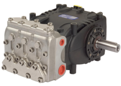
- Fluid Specification: Confirm the correct hydraulic fluid or coolant is being used. Specification mismatch is one of the most common causes of apparent performance failure. For example, the Interpump PUMP W2035 L ATEX is engineered for specific fluid viscosity and contamination control—using incorrect fluid will skew your test results.
- Environmental Conditions: Record ambient temperature, humidity, and altitude at the installation site. These variables affect motor efficiency, seal performance, and fluid viscosity.
Install Measurement Points
You cannot verify performance without instrumentation. Plan measurement points before commissioning begins:
- Pressure Measurement: Install pressure gauges or transducers at inlet (suction) and outlet (discharge). For high-pressure applications like the Pratissoli SN7045 L operating at 210 bar, use calibrated digital pressure transducers rated 25% above maximum expected pressure.
- Flow Measurement: Arrange for temporary flow meter installation. Turbine meters, gear meters, or ultrasonic flow measurement all work—but ensure the meter's range captures your expected flow rate. A meter rated 0–200 L/min will have poor accuracy measuring 5 L/min flows.
- Power Consumption: Connect a power analyzer to the motor terminals. This captures actual kW draw, power factor, and current imbalance—all indicators of mechanical problems.
- Temperature Monitoring: Use infrared thermometers or thermal imaging at the pump casing, motor frame, and discharge lines. Rising temperature indicates internal friction, cavitation, or inadequate cooling.
Section 2: Flow Rate and Pressure Verification Testing
Establishing Baseline Operating Point
Start with low-load testing before ramping to rated conditions:
1. Prime the System: For positive displacement pumps like the Pratissoli KF30, fill suction lines with fluid and bleed air from the system before startup. Air pockets collapse under pressure and produce false vibration and noise readings.
2. Initial Startup: Run at minimum flow (relief valve cracked open) for 5–10 minutes. Monitor discharge temperature. It should rise gradually, not spike. A sudden temperature jump indicates the relief valve is leaking internally, reducing actual flow delivery.
3. Record Zero-Load Condition: With the system flowing but at minimum backpressure (just above atmospheric), measure and record actual flow rate at nameplate motor speed. This is your baseline. If the pump is speed-controlled by a VFD, confirm it's operating at rated frequency (typically 50 or 60 Hz).
Incremental Pressure Loading
Now systematically increase system backpressure:
- Load Step 1 (25% rated pressure): Gradually throttle the discharge until pressure reaches 25% of rated maximum. Measure flow, pressure, and power consumption. Flow should remain nearly constant (positive displacement pump) or decrease slightly (centrifugal pump). Power should increase proportionally with pressure.
- Load Step 2 (50% rated pressure): Continue throttling. For the Interpump W2035 L ATEX, you're targeting 100 bar. Pause for 2 minutes at this point and allow fluid temperature to stabilize before recording final values.
- Load Step 3 (75% rated pressure): Approach 150 bar. Watch for noise or vibration changes. These often signal cavitation, air entrainment, or mechanical wear beginning.
- Load Step 4 (100% rated pressure): Reach full 200 bar. Take measurements over a 10-minute period. Flow should be within ±5% of nameplate, and motor power should not exceed rated kW by more than 10% (accounting for ambient temperature and voltage variations).
Acceptance Criteria for Flow and Pressure
Your acceptance criteria must account for real-world conditions:
- Positive Displacement Pumps: Flow should be within ±3% of nameplate across all pressure steps. The Pratissoli SN7045 L rated at 45 L/min should deliver 43.6–46.4 L/min at rated speed and pressure. Deviation beyond this indicates internal leakage, wear, or cavitation.
- Centrifugal Pumps: Flow varies with system resistance. Plot your measured flow-pressure curve and compare to the manufacturer's pump curve (usually provided in technical datasheets). Your points should fall within ±8% of the published curve.
- Pressure Drop: If discharge pressure at rated speed and load is more than 5 bar below nameplate, suspect inlet restriction, cavitation, or internal wear.
- Motor Current: Power draw should match nameplate ±15%, accounting for fluid temperature. Cold fluid (below 15°C) increases viscosity and power consumption; hot fluid (above 60°C) reduces efficiency.
Section 3: Mechanical Integrity and Efficiency Assessment
Vibration and Noise Baseline Measurement
Unusual vibration or noise during the pressure-loading tests signals mechanical problems before they become failures:
- Cavitation Noise: Sounds like pebbles rattling inside the pump. Indicates inlet pressure is too low (suction lift too high, inlet filter clogged, or fluid level insufficient). Verify suction pressure remains above –0.3 bar; ideally 0 to +0.5 bar.
- Bearing Noise: Grinding or squealing from the motor or pump end. Compare to a reference pump if possible. Bearing wear is progressive; catching it early allows planned replacement during next maintenance window.
- Coupling Misalignment: Loud banging or clunking during startup or shutdown. Stop immediately and call maintenance. Coupling damage spreads quickly.
- Relief Valve Chatter: Rapid pressure fluctuations at discharge (visible on pressure gauge or transducer). Indicates relief valve is cycling or stuck. Document this for investigation—a failed relief valve will limit actual system pressure below nameplate.
Power Consumption Verification
Compare measured power to nameplate across multiple load points:
| Operating Condition | Expected Power Draw | Acceptance Range |
|---|---|---|
| Idle (no load) | ~15–25% nameplate | 10–30% |
| 50% rated pressure | ~55–65% nameplate | 50–75% |
| 75% rated pressure | ~80–90% nameplate | 75–100% |
| 100% rated pressure | 100% nameplate | 85–115% |
If power consumption is consistently 20% above nameplate across all points, suspect mechanical friction (bearing wear, seal drag) or an internal leak forcing the relief valve to work harder. Both require repair before accepting the equipment.
Seal and Leak Inspection
After 30 minutes of operation at rated conditions:
- Visual Inspection: Check for fluid weeping at shaft seals, union connections, and drain ports. Minor dampness is normal; active dripping is not. Collect any leakage in a pan for 5 minutes and measure volume. Acceptable leakage is typically <5 mL/minute for mechanical seals, <20 mL/minute for packing seals.
- Temperature Check: Use an infrared thermometer on seal areas. They should be warm (35–50°C) but not hot (>60°C). Excessive seal temperature indicates friction and imminent failure.
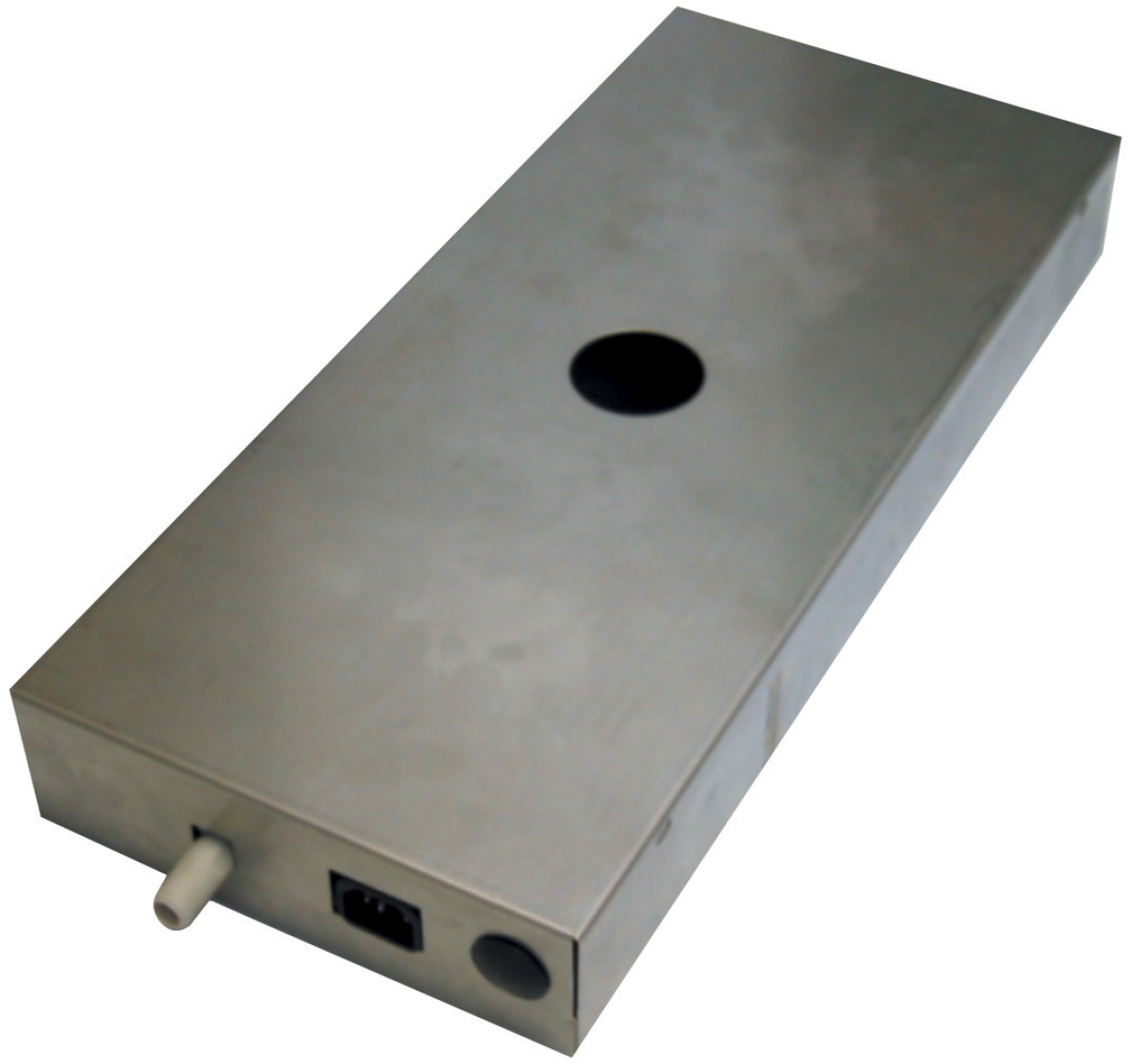
- Suction-Side Inspection: For the Clima Concept Display pump, verify the 5-liter reservoir maintains adequate fluid level throughout the test. Falling fluid level during operation indicates a leak you haven't spotted visually.
Section 4: Documentation and Acceptance Decision
Create a Comprehensive Test Report
Your commissioning test report becomes part of the equipment record and justifies your acceptance or rejection decision:
Essential Report Sections:
1. Equipment Identification: Model, serial number, purchase order number, delivery date
2. Test Parameters: Fluid type and temperature, ambient conditions, test duration, instrumentation used and calibration dates
3. Measured Results Table: Flow, pressure, power, temperature at each load point
4. Comparison to Specification: Show nameplate values alongside measured values with percentage deviation
5. Observations: Noise, vibration, leak rate, seal condition, bearing condition
6. Decision: ACCEPT, ACCEPT WITH EXCEPTIONS, or REJECT
Making the Acceptance Decision
ACCEPT when:
- Flow is within ±5% of nameplate across all pressure points
- Pressure achieved matches nameplate rating
- Power consumption is within ±15% of nameplate
- No cavitation, unusual noise, or bearing wear detected
- Leak rate is <5 mL/minute at seals
- Temperature stabilizes below 60°C during sustained operation
- Minor deviations exist (e.g., flow 7% below nameplate) but the equipment is functionally acceptable for your application
- Document the exception clearly and notify operations that the equipment is operating at slightly reduced capability
- This approach is practical when replacement leads to extended downtime
- Flow deviation exceeds ±8% of nameplate
- Pressure achieved is more than 5 bar below rating
- Cavitation or bearing wear is evident
- Leak rate exceeds 10 mL/minute
- Power consumption exceeds 120% of nameplate
Warranty and Vendor Communication
If you reject equipment or identify defects during testing, immediately notify your supplier with documented evidence. 3G Electric and other reputable distributors support field verification—it protects both parties by catching manufacturing defects early. Provide your vendor with:
- Test report and measured data
- Photographs of pressure/flow gauges during testing
- Serial number and batch information from the equipment
- Request for root cause analysis and replacement or repair timeline
This documentation protects your procurement record and establishes liability clearly.
Practical Summary for Global Operations
Pumps & Compressors performance verification is systematic and measurable. You don't need advanced expertise—you need basic instrumentation, clear acceptance criteria, and disciplined documentation. Whether you're commissioning an Interpump high-pressure pump in Southeast Asia or a condensate pump in Europe, the same testing principles apply.
The investment in field testing during commissioning prevents far more costly failures during operation. Over 35 years, 3G Electric has seen procurement teams who skip this step experience preventable downtime, warranty disputes, and operational safety risks. Those who implement systematic verification protect their operations and build stronger relationships with suppliers.
Start your next commissioning with baseline documentation, install measurement points before startup, conduct systematic pressure loading, and document everything. Your acceptance decision becomes defensible, your operations run reliably, and your vendor relationship remains professional.