Understanding Common Pumps & Compressors Failure Modes
With over 35 years of experience distributing industrial equipment across Southeast Asia, 3G Electric has observed that approximately 70% of Pumps & Compressors failures are preventable through proper diagnostic identification. Maintenance teams must recognize the distinction between mechanical failures, hydraulic anomalies, and control system malfunctions, as each requires fundamentally different troubleshooting approaches.
The most frequently encountered failure modes include cavitation (insufficient inlet pressure), internal leakage (seal degradation), noise and vibration (bearing wear or misalignment), loss of pressure (valve blockage or seal failure), and thermal runaway (cooling system inadequacy). Understanding the physical mechanisms behind each failure type enables your team to implement targeted corrective actions rather than attempting generalized fixes that waste time and resources.
Cavitation occurs when vapor pockets form within the pump chamber due to pressure drops below the fluid's vapor pressure. This creates shock waves that damage impeller surfaces and internal seals, manifesting as distinctive chattering noises and sudden pressure loss. Loss of suction lift, clogged inlet filters, and excessive inlet line restrictions are the primary culprits. Immediate diagnostics require checking inlet pressure gauges and filter condition—blocked filters can reduce inlet pressure by 0.5 bar or more, triggering cavitation in high-speed units like the Pratissoli KF30 high-performance industrial pump operating at 40 kW.
Internal leakage develops when clearances between rotating and stationary components exceed manufacturer tolerances. Wear rings, shaft seals, and spool valves gradually enlarge these gaps, allowing pressurized fluid to bypass load paths. Symptoms include reduced flow at constant pressure, overheating fluid, and slower actuator response. Measurement of actual flow output against nameplate specifications using a calibrated flowmeter is the definitive diagnostic—if the Interpump PUMP AB80 CYL. L rated at 75 L/min now delivers only 65 L/min at rated speed, internal leakage has likely progressed beyond acceptable limits.
Systematic Troubleshooting Flowchart for Pressure Loss Events
When your maintenance team encounters a Pumps & Compressors delivering insufficient system pressure, a structured diagnostic sequence prevents misdiagnosis. Begin by isolating whether pressure loss is occurring at the pump outlet, in the transmission lines, or at the actuator:
Step 1: Verify Pump Input Conditions
- Connect an independent pressure gauge directly to the pump inlet port (not the system gauge)
- Measure inlet pressure; it should match atmospheric pressure (1 bar) for most systems
- If inlet pressure is below 0.8 bar on suction-lift applications, inspect the inlet line for blockages, kinks, or filter saturation
- For submerged inlet tanks, verify fluid level is 150-200 mm above the inlet port
- Slowly open the pump discharge isolation valve while observing pressure buildup on a calibrated gauge
- Pressure should reach rated specification within 2-3 seconds for normal displacement pumps
- If pressure creeps up slowly or fails to reach rated pressure, perform a "dead-head" test by closing all downstream isolation valves and running the pump for 30 seconds while monitoring pressure rise rate
- Abnormally slow pressure rise indicates internal slippage; rapid pressure rise confirms the pump mechanism is mechanically sound
- Close the pump discharge isolation valve and monitor pressure gauge for 60 seconds
- Pressure decay of more than 10 bar indicates external leakage in the transmission circuit
- Pressure decay of less than 2 bar indicates acceptable internal leakage (within manufacturer tolerance)
- If pressure holds steady for 5 minutes, suspect a faulty pressure relief valve allowing backflow
- Gradually introduce load to the system while recording pressure, flow, and pump motor current draw
- For high-pressure applications using units like the Interpump PUMP E1B1614 rated for 160 bar, pressure should stabilize within 5 bar of set-point
- If pressure oscillates by more than 10 bar or motor current exceeds rated nameplate value by 15%, suspect a malfunctioning pressure control valve or improper pump displacement setting
Diagnosing Noise, Vibration, and Thermal Issues
Abnormal acoustic signatures from Pumps & Compressors often precede catastrophic failure by days or weeks, providing a critical window for intervention. Your maintenance team should develop familiarity with normal operating sounds and respond immediately when acoustic characteristics change.
Cavitation Noise Diagnosis:
Cavitation produces a distinctive "gravel grinding" sound, similar to marbles rolling inside the pump casing. This occurs when vapor pockets collapse, generating shock waves. To differentiate from other noise sources, perform the following check: gradually increase system load while listening with a mechanic's stethoscope placed on the pump casing. If the grinding noise intensifies with load increase, cavitation is confirmed. Immediate action: check inlet filter condition (replace if pressure drop exceeds 0.3 bar across the filter element), verify pump inlet line for any restrictions, and confirm fluid level in the source tank is adequate.
Mechanical Noise Diagnosis (Bearing Wear):
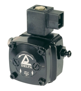
Bearing wear generates a high-frequency squealing or whining that remains constant regardless of system load. This indicates radial or axial bearing clearance has increased beyond acceptable limits. Using a digital vibration meter, measure displacement at the pump bearing housing in vertical and horizontal planes. Values exceeding 7.1 mm/second peak velocity (ISO 20816) indicate bearing replacement is required. For units like the Delta VM1 LL 2.4 pump operating at 3500 rpm, bearing wear accelerates rapidly once threshold vibration levels are exceeded.
Thermal Runaway Diagnosis:
Fluid temperature elevation of more than 10°C above baseline operation within 30 minutes indicates the cooling system cannot dissipate generated heat. Measure outlet fluid temperature using an infrared thermometer and compare against inlet temperature. A temperature differential exceeding 15°C at nominal load suggests inadequate heat exchanger capacity or internal leakage (which converts lost pressure directly into heat). Check cooler fins for blockage from dust accumulation—even a 20% blockage reduces cooling effectiveness by 35%. Verify cooler circulation pump is operating at rated speed and that bypass valves are not open.
Seal and Valve Component Replacement Protocols
Maintenance teams should stock critical seal kits and valve cartridges before failures occur. Based on 35+ years of distributing industrial equipment, we recommend maintaining on-shelf inventory for units in continuous operation.
Shaft Seal Replacement Procedure:
Shaft seals on Pumps & Compressors typically last 3,000-5,000 operating hours before weeping begins. When external fluid leakage appears around the pump shaft, replacement is required. The procedure follows this sequence:
1. Depressurize the system completely and release trapped energy by opening bleed valves
2. Remove the pump from the system (drain fluid into a clean container for filtration or disposal)
3. Support the pump horizontally in a soft-jaw vise
4. Remove the coupling bolts and separate the motor from the pump body
5. Using a seal puller tool, carefully extract the old seal without scratching the shaft surface
6. Clean the seal cavity with a lint-free cloth and inspect the shaft surface with your fingernail—any roughness indicates shaft damage requiring professional regrinding
7. Install the new seal kit using the supplied installation tool; apply a light coat of system fluid to seal lips before assembly
8. Reassemble the pump and motor, torque all fasteners per OEM specifications
9. Prime the pump by rotating the shaft manually 5-10 revolutions before pressurizing
Pressure Relief Valve Troubleshooting:
If your system pressure creeps upward continuously or the relief valve "chatters" (rapidly opens and closes), the internal spool is likely sticking due to fluid contamination. Begin with a fluid sample analysis—if the ISO cleanliness code exceeds 19/17/14, the fluid has deteriorated beyond acceptable limits. Contaminated fluid must be completely drained and replaced. For relief valve correction, follow this sequence:
1. Isolate the relief valve by closing isolation ball valves at its inlet and outlet ports
2. Connect a portable pressure source (hand pump or test gauge) to the valve inlet
3. Slowly increase pressure while observing cracking pressure (the pressure at which the valve first opens)
4. Cracking pressure should occur within ±5% of the valve setting; if deviation exceeds this tolerance, the valve spool is damaged and must be replaced
5. Before reinstalling the valve, flush the entire system through a 3-micron portable filter cart to remove dislodged contamination
Emergency Repair Prioritization for Production Recovery
When critical Pumps & Compressors fail mid-production, maintenance teams face pressure to restore function rapidly. Implementing a structured prioritization matrix prevents costly mistakes and expedites recovery.
Tier 1 Emergency (Production Halted):
If the failed unit drives a critical process with no redundancy, immediate actions include: (1) verify the root cause is the pump and not a downstream blockage (check for tripped relief valves or stuck directional control valves first), (2) contact 3G Electric for rapid component sourcing—we maintain inventory of critical items like the Interpump WS 162 L for high-pressure applications, and (3) deploy a portable replacement pump if available. For the Pratissoli Series, the KF30 pump can be substituted in many systems rated for 200 bar operation, allowing rapid recovery while the original unit is repaired.
Tier 2 Response (Production Degraded):
If backup capacity exists or production can operate at reduced throughput, reduce system pressure by 10-15% to minimize further damage while repair arrangements are finalized. This extends pump life by reducing thermal stress and seal loading.
Tier 3 Planned Maintenance (No Production Impact):
Schedule component replacement during planned maintenance windows. Use this time to perform complete fluid analysis, cooler inspection, and seal kit replacement to prevent cascading failures.
Post-Repair Commissioning and Verification
After completing any major Pumps & Compressors repair, implement a structured commissioning protocol before returning to production loads:
- Pressure verification: Run the unit at 50% load for 15 minutes while recording pressure every 30 seconds; verify no drift exceeds 5 bar
- Flow measurement: Use a calibrated flowmeter to confirm actual flow matches nameplate specification within ±5%
- Thermal profiling: Monitor fluid temperature for 30 minutes; temperature rise should not exceed 3°C per 10 minutes of operation
- Vibration baseline: Record vibration displacement at bearing housings using a digital meter; establish this as the post-repair baseline for trending
- Fluid sampling: Collect a fluid sample for ISO cleanliness verification before full production operation
These verification steps typically require 1-2 hours but prevent premature re-failure and reduce overall downtime risk.