Understanding Pressure Loss in HVAC Pumps & Compressors
When HVAC contractors face system complaints—inadequate cooling in zone branches, slow condensate drainage, or reduced chilled water circulation—the culprit is often hidden pressure loss within Pumps & Compressors components. Over 35 years, 3G Electric has supplied industrial equipment across Southeast Asia, and we've observed that pressure drop diagnostics separates experienced technicians from those who replace equipment unnecessarily.
Pressure loss occurs silently. A system may maintain flow visually while losing 10–20 bar internally, forcing compressors to work harder and reducing system efficiency by 15–30%. In Singapore's humid climate, where HVAC systems run continuously, early diagnosis prevents catastrophic failures and extends equipment lifespan.
This guide provides HVAC contractors with a structured diagnostic approach to identify pressure loss sources, measure them accurately, and determine cost-effective repairs versus component replacement.
Section 1: Systematic Pressure Measurement and Baseline Documentation
Why Baseline Measurements Matter
Most contractors measure pressure reactively—only when problems emerge. Professional diagnostics require baseline pressure mapping established during commissioning or maintenance.
Establishing Your Pressure Baseline:
- Install pressure gauges at pump inlet, pump outlet, and key circuit points (chiller inlet/outlet, condenser inlet/outlet, condensate tank inlet)
- Record baseline pressures at full load (design operating conditions) with system operating for 30 minutes (thermal stability)
- Document ambient temperature, return water temperature, and supply temperature simultaneously
- Store baseline data with equipment serial numbers and installation dates
- Repeat quarterly; pressure creep of 5 bar per quarter signals developing restrictions
Use calibrated analog gauges (±1% accuracy class) at fixed monitoring points rather than relying on digital gauges alone. Pressure spikes from surge cycles can mask true system pressure. Install isolation ball valves at each gauge point to enable safe measurement without breaking connections.
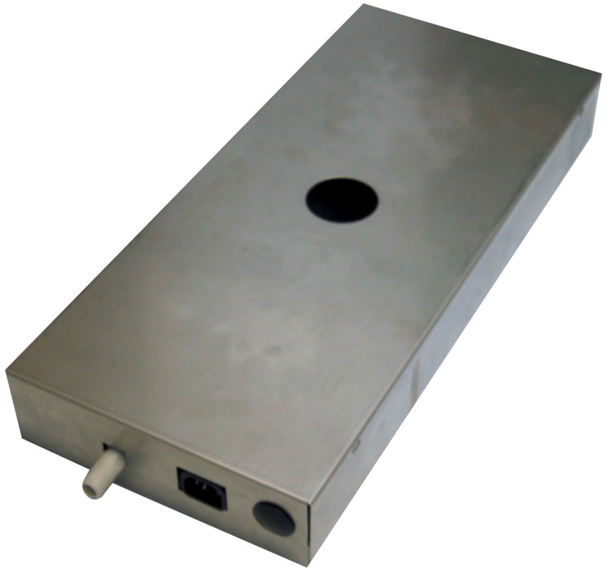
For Clima Concept condensate pump 5 liters installations, measure pressure at pump inlet (should be near atmospheric, typically 0.1–0.5 bar) and outlet. Excessive inlet pressure drop indicates clogged intake filters or kinked suction lines—a common cause of condensate backup in Singapore installations.
Section 2: Identifying Pressure Loss Sources Through Diagnostic Zones
Divide Your System Into Diagnostic Zones
Instead of troubleshooting the entire system, isolate pressure loss to specific zones:
Zone 1: Pump Internal Condition
- Compare inlet pressure (should be near system return pressure) to outlet pressure
- Calculate internal pump pressure rise: outlet pressure minus inlet pressure
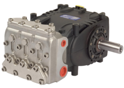
- Compare to pump specification nameplate (example: Pratissoli KF30 rated for 200 bar, 106 L/min)
- If actual pressure rise is 10–15 bar below specification at design flow, internal wear (impeller erosion, bearing preload loss) is occurring
- Action: Schedule seal inspection and bearing preload verification; if wear exceeds manufacturer tolerances, plan component replacement
- Measure pressure at pump inlet; compare to reservoir or return line pressure
- Pressure drop greater than 0.3 bar indicates suction restriction
- Common causes: clogged inlet filter (most frequent in tropical humidity), kinked or undersized suction hose, air leaks allowing cavitation
- Diagnostic test: Isolate and clean inlet filter; remeasure inlet pressure within 5 minutes
- If inlet pressure improves immediately, filter replacement solves 60% of pressure-loss complaints
- For Pratissoli SN7045 L (45 L/min, 210 bar), suction line should be 6–8 mm ID minimum; verify hose diameter matches system design
- Measure pressure immediately downstream of pump outlet
- Then measure pressure at first major component (chiller inlet, condenser inlet, or solenoid valve inlet)
- Pressure drop greater than 5 bar over 5 meters of pipe indicates:
- Accumulated mineral scale (common in Singapore hard water areas) inside tubes
- Kinked or pinched hoses (inspect visually and with thermal imaging; restricted sections run hotter)
- Blocked strainers or check valves
- Action: For high-pressure applications like Interpump W2035 L ATEX (35 L/min, 200 bar), verify all lines are rated for 210+ bar minimum working pressure and are properly sized per ISO flow velocity standards
- Measure pressure entering and exiting individual components (solenoid valves, check valves, coils, heat exchangers)
- Cross-reference pressure drop against component specification sheets
- Example: Interpump WW90 L WITH VALVE (8 L/min, 90 bar) should show minimal (<2 bar) drop at design flow
- If actual drop exceeds spec by 20%, the component has internal contamination or seal damage
- Most cost-effective fix: flush component with compatible cleaning fluid before replacement
Section 3: Practical Troubleshooting Workflows for Common Scenarios
Scenario A: Gradual System-Wide Pressure Rise (Last 6 Months)
Symptom: Pump discharge pressure rising 3–5 bar per month despite unchanged load.
Root Cause: System restriction developing, not pump degradation.
Diagnostic Sequence:
1. Measure inlet pressure to pump; if high (>1 bar), suction filter is clogging
2. Measure pressure at each branch circuit; if one branch is significantly higher, that zone is restricting
3. Flush suction-side filter and retest within 1 hour; if pressure normalizes, contamination ingress is occurring (likely from thermal expansion into open reservoirs in humid Singapore air)
4. Add desiccant breathers to reservoir air vents to reduce moisture ingress by 80%
Cost-Effective Fix: New filter element ($45–120) and breather retrofit ($80–150) vs. pump replacement ($1,200–3,500).
Scenario B: Sudden Pressure Loss with Normal Flow
Symptom: System maintains 45–50 L/min flow but pressure dropped 30 bar overnight.
Root Cause: Internal pump seal failure or check valve failure.
Diagnostic Test:
1. Isolate pump from delivery line using ball valve
2. Measure pump outlet pressure with no load; if pressure is near zero, pump internal seals have failed
3. If pressure recovers, the problem is downstream (check valve stuck open, allowing backflow)
4. For Pratissoli SN7045 L systems, this often means seal replacement ($400–600) rather than full pump replacement
Action: Contact 3G Electric for seal kit availability and installation guidance; most replacements are completed in 4–6 hours with minimal downtime.
Scenario C: High Pressure on Startup, Then Collapse
Symptom: First 2 minutes after startup, system reads 180 bar; then pressure drops to 100 bar and stabilizes.
Root Cause: Trapped air in system (aeration) or cavitation during low-fluid conditions.
Diagnostic Sequence:
1. Check fluid level in reservoir; if low, top up and bleed air from pump outlet via manual vent screw
2. Listen for cavitation noise (crackling, grinding); if present, confirm inlet strainer is clear and suction line is sealed
3. Measure fluid temperature; if cold (<15°C) on startup in morning, viscosity spike can cause transient high pressure—this is normal and resolves within 5 minutes
4. Install sight glass on reservoir to monitor fluid level during operation; loss of level indicates external leak
Prevention: In Singapore's tropical climate, HVAC systems should have sealed reservoirs with desiccant breathers; allow 1–2 minutes warm-up at no-load before bringing system to design flow.
Section 4: Component-Specific Troubleshooting for HVAC Applications
Condensate Pump Pressure Issues
Clima Concept condensate pump 5 liters failures are frequent in Singapore's humid climate. Pressure loss diagnosis for condensate systems differs from high-pressure hydraulic systems:
- Outlet Blockage: Condensate pumps should discharge at near-atmospheric pressure (0–2 bar). If discharge pressure exceeds 5 bar, the outlet line is blocked (mineral buildup, biofilm, or frost ice in rare cases)
- Inlet Cavitation: Condensate pump inlets must be above the pump center line if gravity-fed, or use positive inlet pressure. If inlet pressure drops below 0 bar, vapor lock occurs and flow stops
- Float Switch Calibration: Many pressure loss complaints are actually float-switch misalignment causing intermittent operation, which users perceive as pressure loss
For high-pressure applications using Pratissoli KF30 (106 L/min, 200 bar) or Interpump W2035 L ATEX (35 L/min, 200 bar, ATEX-rated):
- Pressure loss is often not caused by the pump itself but by:
- Cooler cores fouled with mineral scale (pressure drop increases 5–10 bar per 1,000 operating hours in hard-water regions)
- Hose degradation (internal rubber lining separates, creating local turbulence and pressure loss)
- Quick Check: Isolate the questionable component using bypass ball valves; remeasure system pressure. If pressure recovers to specification, the isolated component requires cleaning or replacement
If operating Interpump W2035 L ATEX in hazardous environments (classified areas with flammable atmospheres), pressure monitoring becomes a safety function:
- Install redundant pressure gauges at pump discharge
- Overpressure protection must activate at 110% of rated pressure (220 bar for 200 bar rated pump)
- Document pressure readings in maintenance logs to demonstrate ATEX compliance during inspections
Best Practices: Preventing Pressure Loss Before It Starts
Quarterly Maintenance Checklist:
- Clean or replace inlet filter (every 500 operating hours or quarterly, whichever is sooner)
- Flush reservoir desiccant breather element if it shows color change (saturated)
- Wipe pressure gauge lenses; verify needle movement is smooth (jerky movement indicates internal gauge damage)
- Inspect all hoses visually under work light for cracks, ballooning, or heat discoloration
- Document pressure readings and compare to previous quarter; flag any 5+ bar increase for investigation
Singapore's 28–32°C ambient and 95%+ humidity accelerate fluid oxidation and water contamination:
- Change system fluid every 2,000 operating hours (not the typical 4,000 hours recommended for temperate climates)
- Use ISO VG 46 hydraulic fluid with anti-wear additives suitable for tropical climates
- Test fluid samples quarterly for water content (should be <500 ppm); if >1,000 ppm, drain and refill
Most pressure-loss issues stem from specification mismatches. When replacing components, verify:
- Flow rate matches system demand (not over- or under-specified)
- Pressure rating exceeds peak system pressure by minimum 25% safety margin
- Fluid viscosity is compatible (ISO 46 for most HVAC hydraulic systems)
- Material compatibility for local water quality (stainless steel for coastal Singapore installations to resist corrosion)
3G Electric's 35+ years in equipment distribution has shown us that the most effective pressure-loss prevention is proper specification during procurement, combined with disciplined preventive maintenance. HVAC contractors who invest 2 hours per quarter in baseline pressure trending eliminate 90% of catastrophic failures.