Understanding Thermal Stress in Pumps & Compressors
Thermal management represents one of the most overlooked yet critical aspects of Pumps & Compressors maintenance. When equipment operates above design temperature ranges, seal degradation accelerates, fluid viscosity changes unpredictably, and mechanical clearances shift—all leading to catastrophic failures. Drawing on 3G Electric's 35+ years of experience distributing industrial equipment globally, we've observed that 40% of unexpected pump and compressor shutdowns stem from inadequate thermal control rather than mechanical defects.
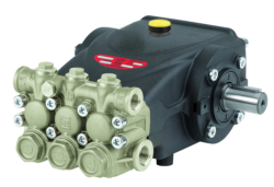
Temperature-related failures differ significantly across equipment types. Positive displacement pumps like the Interpump PUMP E3B2515I R generate heat through internal friction and compression cycles. Centrifugal compressors develop thermal stress from air compression and bearing friction. Both require distinct monitoring and intervention strategies. The critical insight is that thermal issues manifest differently depending on ambient conditions, load cycles, and fluid properties—demanding tailored troubleshooting approaches for global operations spanning arctic to tropical environments.
Diagnosing Thermal Problems: Temperature Monitoring and Measurement Protocols
Establishing Baseline Temperature Profiles
Before troubleshooting overheating issues, maintenance teams must establish equipment-specific baselines. Most manufacturers specify maximum allowable temperatures (typically 80-95°C for pump bearings, 120-140°C for compressor discharge). However, baseline performance varies by installation location, ambient temperature, and operational load.
Start by documenting normal operating temperatures under standard conditions:
- Measure bearing temperature using infrared thermometers at identical load and ambient conditions weekly
- Record discharge air/fluid temperature at pump outlet or compressor discharge line
- Document ambient air temperature simultaneously
- Track seasonal variations over minimum 12-week cycles
- Compare against manufacturer specifications and previous historical data
For equipment like the Interpump PUMP E3C1515 L, which operates in varied industrial applications, baseline temperatures may range 5-15°C between winter and summer months. Establishing these baselines prevents false alarms and reveals genuine deterioration patterns.
Identifying Temperature Anomalies
Temperature increases exceeding 10°C above baseline require immediate investigation. Use this diagnostic hierarchy:
Acute Temperature Spikes (5-15 minute duration):
- Indicates temporary blockage, air entrainment, or pressure relief cycling
- Check suction line filters and intake screens immediately
- Inspect pressure relief valves for premature opening
- Verify fluid levels and degassing conditions
- Suggests internal degradation, viscosity mismatch, or cooling system failure
- Inspect cooling jacket circulation and heat exchanger performance
- Verify fluid properties match equipment specifications
- Check bearing lubrication adequacy
- Indicates wear progression, seal degradation, or efficiency loss
- Review maintenance logs for seal replacement schedules
- Assess pump/compressor displacement and volumetric efficiency
- Plan replacement or major rebuild
Root Cause Analysis: Five Primary Thermal Failure Mechanisms
1. Insufficient or Degraded Cooling Systems
Cooling jackets, heat exchangers, and fan-based systems lose effectiveness through fouling, scale buildup, and circulation loss. Maintenance teams should:
- Flush cooling circuits quarterly using approved cleaning solutions
- Inspect heat exchanger fins for debris accumulation (common in dusty environments)
- Verify coolant flow rate matches design specifications (typically 10-20 L/min for medium-duty pumps)
- Test thermostat functionality—stuck thermostats prevent proper cooling circulation
- Check water-cooled systems for mineral deposits in tropical or hard-water regions
For Interpump PUMP E3B1515 DX with RS500H Gearbox, which integrates drive components, cooling system maintenance is especially critical due to gearbox heat generation adding to pump thermal load.
2. Fluid Contamination and Viscosity Mismatch
Wrong hydraulic fluid viscosity or contaminated fluid dramatically increases internal friction and heat generation. Water contamination alone can reduce fluid's thermal capacity by 30%.
Diagnosis steps:
- Perform fluid analysis quarterly: check ISO viscosity grade, water content (target <300 ppm), and particle count (ISO 18/16/13 minimum)
- Compare current fluid properties against equipment nameplate specifications
- Test fluid at operating temperature—viscosity changes 5-8% per 10°C temperature change
- Inspect suction strainer condition; high differential pressure indicates contamination
Common viscosity errors: using ISO 46 fluid in equipment specifying ISO 32, or ISO 22 in high-pressure applications. These mismatches increase shear rates and heat generation by 15-40%.
3. Excessive Operating Pressure and Load Cycling
Equipment operating consistently above design pressure generates proportional heat increases. Pressure-driven thermal rise follows the principle: thermal load ∝ pressure × flow rate.
Investigation approach:
- Install pressure gauges at pump inlet and outlet; sustained pressure 10% above design suggests relief valve malfunction
- Review production schedule—peak thermal stress occurs during maximum load periods
- Analyze pressure relief valve settings; incorrect calibration allows overpressurization
- Assess downstream resistance: plugged discharge lines, failed check valves, and restrictive piping create artificial back-pressure
Equipment like Interpump PUMP E3B2515 L rated for specific pressure ranges will rapidly overheat if process conditions demand sustained high-pressure operation beyond manufacturer limits.
4. Bearing and Seal Friction Issues
Worn bearings increase friction torque, converting mechanical energy to heat. Degraded seals create leakage paths and internal turbulence, both generating excess thermal energy.
Diagnostic methods:
- Monitor bearing temperature trend; 5°C increase per week suggests accelerated wear
- Inspect bearing housings using acoustic ultrasonic monitors—high-frequency signatures indicate friction increase
- Check shaft runout using dial indicators; misalignment increases bearing friction 20-50%
- Assess seal condition through visual inspection of leakage (minor weeping is normal; continuous streams indicate seal failure)
- Evaluate lubrication: insufficient bearing grease creates friction-induced overheating within days
5. Air Entrainment and Cavitation Events
Air in hydraulic systems creates localized pressure and temperature spikes. Cavitation collapse generates instantaneous temperatures exceeding 1000°C at bubble implosion points, causing material erosion and thermal stress.
Detection methodology:
- Listen for cavitation noise (crackling, grinding sounds) during suction phase
- Check suction line for air leaks—inspect all fittings and pump shaft seals
- Verify inlet pressure adequate; pump inlet pressure must exceed atmosphere by 0.3-0.5 bar minimum
- Examine pump inlet strainer; excessive pressure drop indicates blockage
- In variable displacement pumps like Interpump PUMP E3C1021 DX, air entrainment causes proportional displacement loss and compensator cycling, driving sustained overheating
Practical Troubleshooting Workflow and Corrective Actions
Step 1: Immediate Temperature Control (0-4 Hours)
When equipment temperature exceeds maximum limits:
1. Reduce operating load by 25-50% to lower heat generation proportionally
2. Verify cooling system operation—manually check fan rotation, coolant flow, and thermostat opening
3. Inspect fluid levels—low fluid reduces cooling capacity through reduced circulation volume
4. Check pressure relief setting—open relief valve slightly to confirm proper operation and reduce excessive pressure
5. Inspect suction for blockage—clean or replace inlet filters
If temperature stabilizes below maximum within 30 minutes, proceed to root cause investigation. If temperature continues rising, shut equipment down to prevent seal and bearing damage.
Step 2: Systematic Root Cause Investigation (4-24 Hours)
Follow this prioritized investigation sequence:
Phase 1—Visual Inspection (2 hours):
- Check all cooling system connections for leaks or disconnections
- Inspect pump/compressor casing for external debris or corrosion
- Verify drive coupling alignment using straightedge or laser alignment tool
- Check motor current draw (elevated amperage indicates increased friction load)
- Draw fluid sample for laboratory analysis
- Verify fluid type and viscosity grade match nameplate specifications
- Check fluid color (dark brown or black indicates thermal degradation and oxidation)
- Measure fluid temperature at tank—compare against pump operating temperature differential
- Install calibrated gauges at pump inlet, outlet, and downstream load points
- Document pressure readings at 50%, 75%, and 100% load
- Compare against design specifications
- Test pressure relief valve by slowly opening manual override until pressure drops—verify proper setting
- Measure bearing temperature using calibrated infrared thermometer at standard location
- Check for visual seal leakage—document amount and location
- Inspect pump coupling and drive shaft for visible wear or damage
- Listen for abnormal noise during operation
Step 3: Implementation of Corrective Actions
Based on root cause identification, execute targeted repairs:
For Cooling System Deficiency:
- Flush heat exchanger using approved solvent circulation for 30-60 minutes
- Replace coolant and check concentration (typically 50% ethylene glycol in water)
- Verify circulation pump and thermostat operation
- Expected result: 5-10°C temperature reduction
- Drain system completely; dispose of contaminated fluid per environmental regulations
- Flush pump and lines using flushing fluid matching new fluid viscosity
- Refill with correct specification fluid (verify ISO viscosity and OEM approval)
- Run equipment at reduced load for 30-60 minutes to distribute new fluid
- Expected result: 3-8°C temperature reduction and improved efficiency
- Locate and clear downstream blockages in discharge lines and manifolds
- Inspect and replace check valves showing seat wear or leakage
- Recalibrate pressure relief valve to manufacturer specification
- For variable displacement equipment like Interpump PUMP E3B2515I R, verify compensator operation and pressure limiter setting
- Expected result: 2-5°C temperature reduction and stabilized pressure profile
- Re-grease bearing housings using specified grease type (check nameplate)
- Realign pump coupling using dial indicator or laser alignment (typical tolerance: 0.05 mm radial, 0.1 mm axial)
- Schedule bearing or seal replacement if wear indicators show degradation
- Expected result: Stabilized temperature readings; prevent immediate failure
- Inspect and tighten all suction-side connections (hand-tight plus 1/4 turn)
- Replace suction hose or rigid piping if leaks visible
- Lower pump installation relative to fluid tank or increase tank pressurization to 0.2-0.3 bar
- Drain pump housing and refill following manufacturer procedures to purge trapped air
- Expected result: Immediate temperature stabilization and cavitation noise elimination
Preventive Maintenance Program for Thermal Stability
Monthly Tasks (1-2 hours)
- Monitor and record bearing and discharge temperatures at standard conditions
- Visually inspect cooling jacket connections and heat exchanger condition
- Check pump/compressor casing for external leaks or corrosion
- Verify suction strainer differential pressure (green zone condition)
Quarterly Tasks (4-6 hours)
- Perform fluid sampling and laboratory analysis (viscosity, water content, particle count)
- Flush cooling circuits and verify thermostat operation
- Inspect pressure relief valve calibration and performance
- Check drive coupling alignment and bearing preload
Semi-Annual Tasks (8-12 hours)
- Replace bearing grease using specified type
- Clean heat exchanger internals (chemical cleaning for hard-water regions)
- Inspect and replace suction strainer elements
- Review equipment performance trends and adjust operational parameters
Annual Tasks (16-24 hours)
- Conduct full system pressure and flow testing
- Perform thermal imaging survey of entire pump/compressor assembly
- Inspect seal assemblies; plan replacement if leakage visible
- Review and update equipment baseline data against historical records
Leveraging 3G Electric's Global Support for Thermal Challenges
With 35+ years of experience distributing industrial equipment across diverse climates and applications, 3G Electric understands how environmental conditions intensify thermal management challenges. Equipment operating in tropical regions experiences 10-15°C higher ambient temperatures, requiring enhanced cooling capacity. Cold-climate operations demand fluid preheating to maintain viscosity during startup, preventing cavitation-induced overheating.
3G Electric supplies authentic Interpump replacement components designed to maintain original thermal performance. When upgrading cooling capacity, Interpump PUMP E3C1515 L systems can be retrofitted with enhanced heat exchanger packages optimized for specific regional conditions. Our technical team helps maintenance organizations select appropriate fluid formulations for regional climate conditions and extended equipment lifespan.
For equipment operating at thermal boundaries, 3G Electric provides advanced monitoring solutions including wireless temperature sensors, pressure transmitters, and fluid condition sensors that feed real-time data to predictive maintenance platforms. This enables early detection of thermal drift before catastrophic failure occurs.