Understanding Pumps & Compressors Alignment Fundamentals
Misalignment in Pumps & Compressors represents one of the most frequently overlooked failure mechanisms in industrial operations. With over 35 years of experience distributing and supporting industrial equipment across Asia-Pacific, 3G Electric has documented that approximately 60% of premature pump and compressor failures originate from angular, parallel, or combined shaft misalignment—yet many operators treat symptoms rather than root causes.
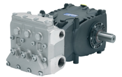
Alignment problems manifest differently depending on equipment type and severity. In centrifugal pumps like the Pratissoli KF30 high-performance industrial pump (106 L/min, 200 bar), misalignment stresses the mechanical seal and bearing assemblies. In positive displacement pumps such as the Pratissoli SS71153 industrial pump (122 L/min, 160 bar), misalignment creates internal pressure spikes and premature gear wear. Rotary compressors experience similar degradation patterns but with added complications from dynamic pressure cycling.
The fundamental challenge: misalignment loads aren't always visible during operation. A motor-to-pump coupling that appears acceptable to the naked eye may impose 500+ kg of side load on bearing assemblies, accelerating failure timelines from 18 months to 3 months. Industrial professionals in Singapore's petrochemical, water treatment, and manufacturing sectors increasingly recognize alignment verification as a mandatory commissioning and preventive maintenance step.
Diagnostic Methods: Detecting Alignment Problems Before Failure
Visual and Tactile Inspection Techniques
Begin with offline diagnostics before running equipment:
- Coupling Gap Assessment: Uncouple the motor from the pump manually (with power isolated and lockout/tagout applied). Rotate the pump shaft slowly by hand while observing coupling fit. Excessive radial play (>0.5 mm on couplings under 15 kW) indicates bearing wear or machining drift. Document baseline measurements for future comparison.
- Straightedge and Feeler Gauge Method: Place a straightedge across the motor and pump shaft flanges. Insert feeler gauges between the straightedge and shaft surfaces at four cardinal points (0°, 90°, 180°, 270°). Acceptable angular misalignment is typically <0.05 mm/25 mm of coupling length for flexible couplings; rigid couplings demand <0.02 mm tolerance.
- Paint Transfer Test: Apply a thin layer of prussian blue or layout fluid to the pump shaft coupling face. Bring the motor coupling into contact, then separate. Examine paint transfer patterns—uniform coverage indicates good axial alignment; concentrated transfer at 12 o'clock or 6 o'clock signals parallel offset.
Vibration Analysis Protocol
Operating equipment provides real-time diagnostic data through vibration signature analysis:
1. Baseline Measurement: Establish vibration signatures immediately after commissioning using a portable vibrometer (acceleration range: 0.1–20 g, frequency range: 5–5000 Hz). Record readings at bearing housings on the motor and pump.
2. Misalignment Signatures: Parallel misalignment produces elevated vibration at 1× running speed (1X) with distinct 2X component. Angular misalignment generates high 2X and 3X harmonics. Typical thresholds:
- Acceptable: <2.8 mm/s RMS (ISO 10816-3 Zone A)
- Caution: 2.8–7.1 mm/s (Zone B) — schedule maintenance within 30 days
- Alert: 7.1–18 mm/s (Zone C) — reduce load, plan shutdown within 7 days
- Fault: >18 mm/s (Zone D) — stop equipment immediately
3. Phase Analysis: Use dual-channel vibration meters to measure phase relationship between motor and pump mounting locations. Angular misalignment typically shows 180° phase difference between opposing bearing points; parallel misalignment shows near-zero phase difference.
Thermal and Oil Analysis Indicators
Misalignment stress manifests chemically before mechanical failure becomes obvious:
- Temperature Trending: Monitor bearing and coupling temperatures via infrared thermography during monthly inspections. Misalignment increases friction, raising bearing temperatures 10–25°C above baseline. A bearing running at 95°C when previously stable at 75°C signals developing mechanical stress.
- Oil Degradation Markers: For pumps with reservoirs (like Pratissoli MW40 high-performance industrial pump systems operating at 211 L/min and 210 bar), submit oil samples quarterly. Elevated iron (>200 ppm) and copper (>50 ppm) concentrations indicate accelerated bearing or gear wear—common consequences of misalignment stress.
Correction Procedures and Practical Solutions
Step-by-Step Realignment Process
Equipment Required:
- Laser alignment tool (dial indicator method acceptable for low-speed applications <1500 rpm)
- Straightedges, feeler gauges, dial indicators
- Soft-face mallet
- Torque wrench (coupling bolt specifications vary by model)
- Safety lockout/tagout kit
1. Establish Reference Plane: Secure the pump in position as the fixed reference point. Most installations keep the pump permanently mounted while adjusting the motor.
2. Horizontal Alignment (Parallel): Using a laser alignment system, project a reference line along the pump shaft. Measure deviation of the motor shaft at the coupling. Calculate required motor movement:
- Offset at motor position = (measured deviation × distance to coupling) ÷ distance between measurement points
- Move motor vertically using shim adjustment or adjustable feet. For every 0.1 mm vertical adjustment at the coupling, calculate required shim thickness based on feet spacing.
3. Vertical Alignment (Angular): Measure axial offset by rotating the laser head 90°. Adjust motor tilt using upper and lower adjustable feet. Typical adjustment: 0.05 mm per full turn of a standard adjustment bolt.
4. Final Verification: Re-measure at two axial positions on the coupling (near motor, near pump) to confirm parallel alignment. Cross-check with feeler gauge method to validate laser readings.
5. Coupling Installation: Install flexible coupling with equal gaps (±0.5 mm) on both shafts. Tighten bolts in star pattern to manufacturer torque specification (typically 25–40 N·m for mid-range couplings). Do not exceed specification—over-torquing reduces coupling flexibility and can cause bolt fatigue failure.
Real-World Scenario: Pratissoli Pump Series Application
A Singapore water treatment facility operating Interpump PUMP E1D1808 L gear pumps (8 L/min at 180 bar) experienced seal failure at 4-month intervals instead of the expected 24-month service life. Initial investigation pointed to seal compatibility; however, vibration analysis (2X harmonic dominance at 5600 rpm) revealed angular misalignment of 0.15 mm/25 mm.
After laser realignment (corrected to 0.02 mm/25 mm specification) and verification using accelerometer measurements (vibration reduced from 8.2 mm/s to 2.1 mm/s), seal life extended to 22 months on subsequent installations. This 450% improvement in seal longevity prevented $180,000+ in annual unplanned downtime across the facility's pump fleet.
Coupling Selection and Installation Best Practices
Choosing the Right Coupling for Misalignment Tolerance
Different coupling types accommodate misalignment differently:
- Rigid Couplings: Zero misalignment tolerance; smallest footprint; use only where perfect alignment is guaranteed (rare). Applicable to Interpump ET1C1612 SX*D20 direct-drive installations.
- Flexible Elastomeric Couplings: Accommodate 0.5–2.0 mm parallel offset and 0.5–1.5° angular misalignment. Suitable for most industrial pump installations under 100 kW. Cost-effective and widely available in Singapore.
- Flexible Disc/Diaphragm Couplings: Superior angular tolerance (2–3°); lower backlash; higher cost. Recommended for precision applications and high-speed compressors.
- Oldham Couplings: Accommodate parallel offset up to 5 mm; zero angular tolerance; low torsional rigidity. Used in applications requiring significant parallel adjustment capability.
Post-Installation Verification
After coupling installation, perform these checks before resuming normal operation:
1. Rotate shafts through full revolution by hand; confirm smooth rotation without binding.
2. Measure coupling run-out using dial indicator (acceptable: <0.05 mm TIR—total indicated run-out).
3. Re-verify vibration signature at 25%, 50%, 75%, and 100% load to confirm alignment stability under operating stress.
4. Document all measurements and store in equipment history file for future reference.
Preventive Maintenance Schedule and Monitoring
Industrial professionals should implement a structured alignment maintenance program:
Monthly: Visual inspection of coupling condition, straightedge verification of coupling gap geometry.
Quarterly: Vibration signature capture at bearing locations; thermal imaging of motor and pump mounts; oil analysis (for reservoir-equipped pumps).
Annually: Full laser alignment verification; coupling inspection for elastomer degradation or elastomeric element wear.
On-Demand: Whenever vibration levels exceed ISO Zone B (7.1 mm/s), when bearing temperatures rise >15°C above baseline, or following unplanned downtime events.
With 35+ years supporting industrial operations across Singapore and Southeast Asia, 3G Electric recommends treating alignment verification as foundational commissioning work rather than optional maintenance. Early investment in precision alignment eliminates the most common failure mode affecting Pumps & Compressors performance and longevity.