Pilot Light & Solenoid Valve Integration: Commissioning & Maintenance Essentials for Gas Regulation Systems
For maintenance teams and service engineers managing industrial gas burner systems, the reliability of your ignition and control architecture depends on seamless integration between pilot lights and solenoid valve circuits. This guide walks you through the practical mechanics of pilot light and solenoid valve interaction, commissioning workflows, and hands-on troubleshooting strategies that apply across global industrial facilities—from food processing lines to ceramic kilns and pharmaceutical manufacturing environments. Understanding how these components work together, and how to maintain them properly, directly impacts system uptime, safety, and operational efficiency.
How Pilot Lights and Solenoid Valves Work Together in Gas Regulation
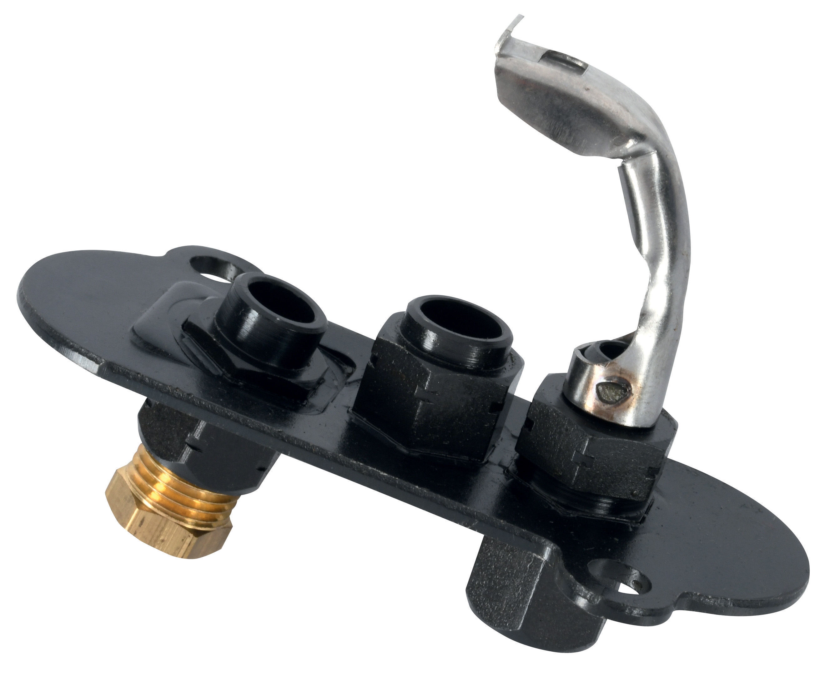
A pilot light serves two critical functions in modern gas regulation systems: it provides continuous ignition for the main burner flame, and its thermocouple generates a small electrical current that energizes the solenoid valve coil, keeping the main gas supply valve open. This is a fail-safe design—if the pilot flame extinguishes, the thermocouple cools immediately, current stops flowing, and the solenoid valve spring returns the valve to its closed position, cutting off gas supply to prevent unsafe accumulation.
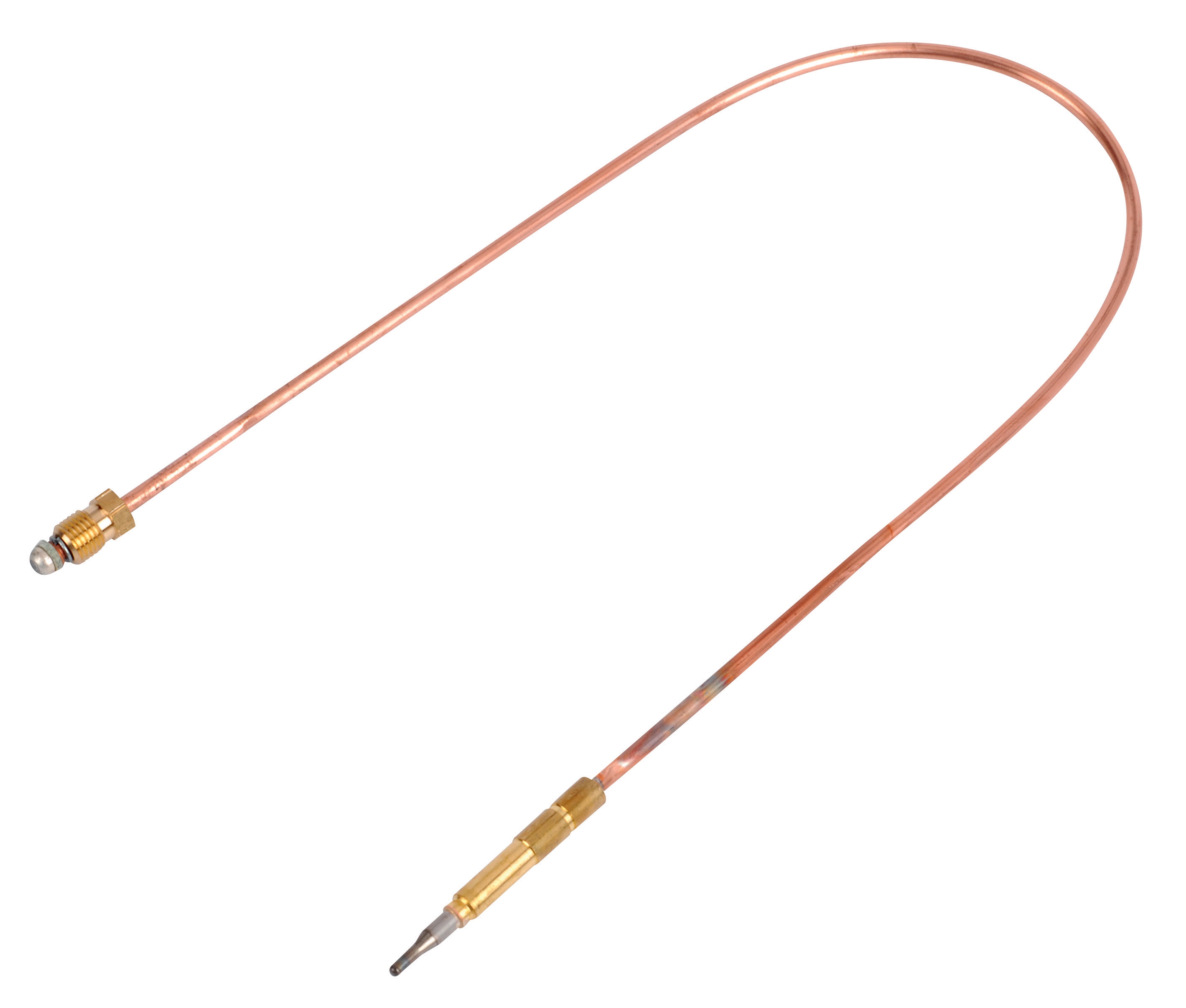
The thermocouple is a thermoelectric device that produces voltage when heated. A single-flame pilot burner generates approximately 25–30 mV under normal operating conditions. This low-voltage signal travels through a control circuit to the solenoid valve coil, which electromagnetically holds open a safety shutoff valve. When you press the pilot ignition button on your system, you manually open a small pilot gas valve, light the pilot with an igniter plug, and allow the thermocouple to heat up. Once the thermocouple reaches full temperature (typically 10–15 seconds), you release the ignition button, and the pilot flame itself—now sustained by gas flowing through the pilot supply line—maintains the thermocouple temperature.
This thermoelectric supervision principle protects against catastrophic failure modes: if the pilot flame blows out due to drafts, vibration, or component wear, gas supply stops automatically without requiring external power. The solenoid valve responds within milliseconds. This architecture is fundamental to EN 161 compliance for industrial burner safety across Europe and adopted globally.
Technical Specifications and Component Selection for Integrated Systems
Selecting compatible pilot light and solenoid valve components requires attention to electrical characteristics, gas flow capacity, and physical dimensions.
Pilot Light Specifications: The CBM pilot light model 0140026 is a single-flame burner designed for silent operation with exceptional corrosion resistance—critical for humid environments or facilities near coastal areas. It features aluminium oxide igniter plugs that withstand thermal shock and mechanical impact, and allows rapid thermocouple substitution without disassembling the burner housing. The thermocouple connector is standardized to accept SIT-specification thermocouples, ensuring interchangeability during field maintenance. Key advantage: its compact footprint and low gas consumption (typically 0.5–1.0 m³/h) make it suitable for both new installations and retrofits.
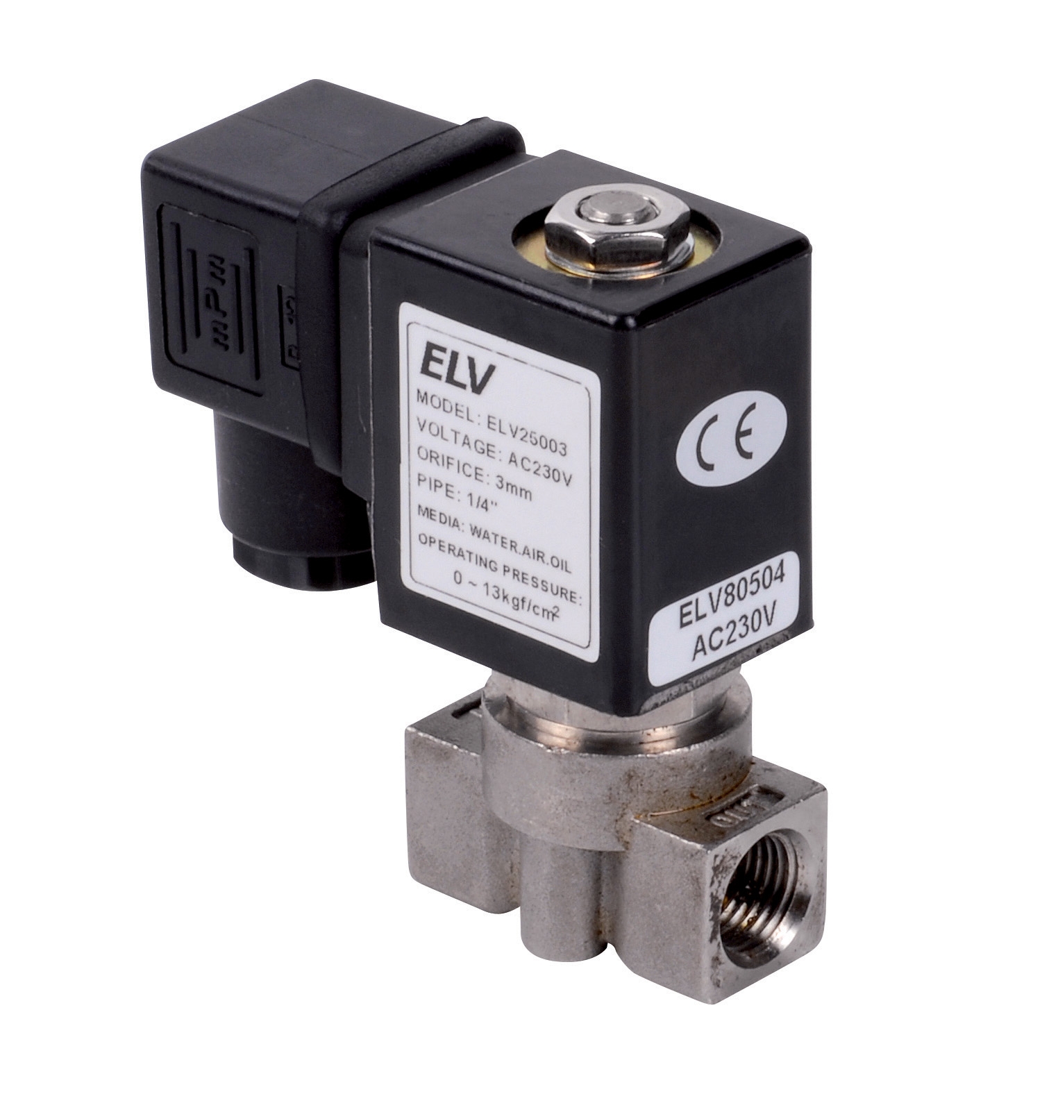
Solenoid Valve Selection for Pilot Circuits: The CBM Bronze solenoid valve 3/4" 220V is designed for direct-acting operation with zero differential pressure requirement, meaning it opens reliably even when inlet and outlet pressures are nearly equal. Its Viton seal material resists degradation from both natural gas and LPG, and the 220V coil voltage is standard across European and global industrial facilities. The cv value of 7.6 ensures adequate pilot gas flow without excessive pressure drop. Power consumption is only 4.5 VA, reducing electrical load on facility wiring—important in facilities with multiple parallel solenoid valve circuits.
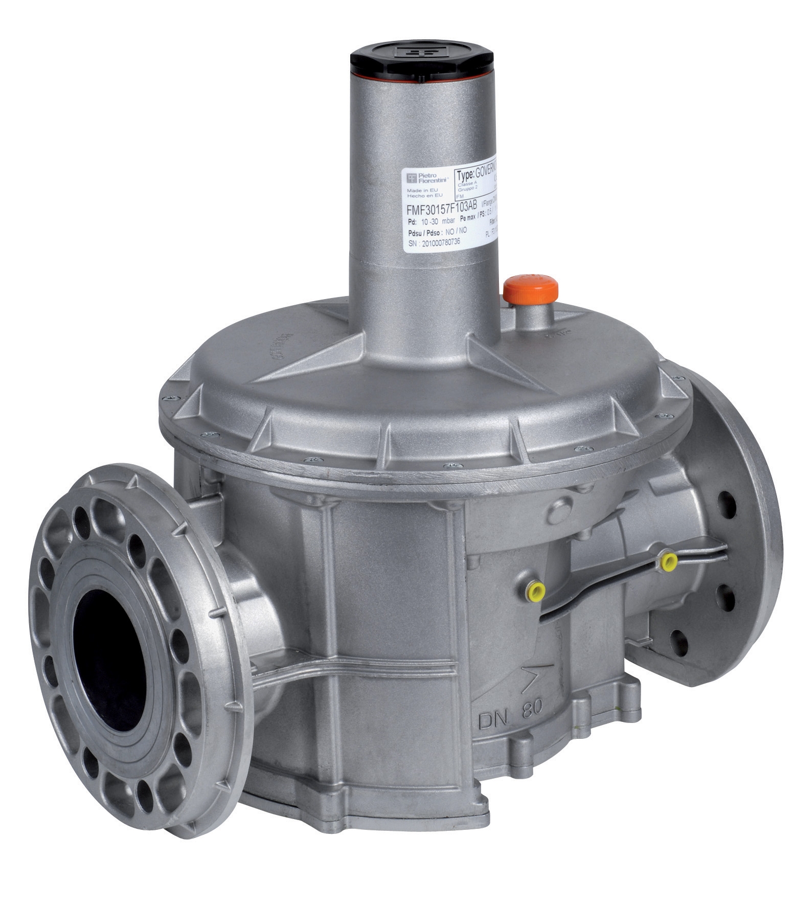
For safety-critical main burner gas supply, the CBM MVD 5100/5 230V valve provides rapid closure (less than 1 second opening time) with integrated 1 mm filter mesh to protect downstream burner nozzles. Its 200 bar maximum pressure rating accommodates high-capacity industrial burners operating at elevated gas supply pressures. The 230V AC coil voltage aligns with standard industrial facility wiring in most global regions.
The CBM MBDLE 407 B01.S52 valve represents a modular integrated approach: it combines rapid closure solenoid function with slow opening mechanics, useful in applications requiring controlled gas ramp-up to prevent flame instability. G 1/8 DIN ISO 228 connection sizing fits compact multifunctional gas blocks where space is constrained.
Real-World Commissioning and Integration Workflows
Scenario 1: New Industrial Burner Installation (Food Processing Facility)
You are commissioning a 100 kW modulating burner in a food processing facility's steam generation system. The installation includes a pilot light assembly, main gas solenoid valve, and pressure regulator. Sequence:
- Verify mechanical connections: Confirm all NPT and flanged joints are torqued to specification and leak-tested with soapy water.
- Thermocouple continuity: Using a multimeter on the resistance setting, verify the thermocouple shows 0–5 ohms resistance when at room temperature. An open circuit (infinite resistance) indicates internal fracture.
- Pilot light ignition: Open the manual pilot gas isolating valve. Press and hold the pilot ignition button. After 3–5 seconds, you should hear the igniter plug clicking and smell raw gas. Continue holding for 10–15 seconds until the pilot flame is visible and the thermocouple begins heating.
- Thermocouple voltage measurement: Using a millivolt meter, measure voltage across the thermocouple terminals. Under steady flame, expect 25–35 mV. Below 20 mV indicates insufficient thermocouple heating—check flame position relative to thermocouple tip.
- Solenoid valve response: Release the ignition button. The solenoid valve coil should now be energized by thermocouple current and hold the pilot gas valve open. If it closes, the thermocouple is not generating adequate voltage—reposition the pilot light or clean the thermocouple tip.
- Main burner ignition: Once the pilot is stable, open the main gas supply slowly while holding the burner control knob in the "on" position. The main flame should ignite from the pilot within 2–3 seconds.
Scenario 2: Troubleshooting Intermittent Pilot Flame Extinction (Ceramic Kiln Facility)
The pilot flame repeatedly extinguishes after 5–10 minutes of operation, causing the solenoid valve to close and shutting down the kiln. Possible causes and diagnostic steps:
- Thermocouple tip fouling: Pilot flames exposed to dust or salt spray can accumulate deposits on the thermocouple tip, reducing heat transfer. Clean gently with a fine emery cloth—do not scratch the surface.
- Pilot gas pressure too high: Excessive pilot gas pressure can lift the flame away from the thermocouple. Check the pilot gas regulator setting; typical values are 3–5 mbar. Reduce if necessary.
- Thermocouple cooling due to airflow: If the kiln burner location is exposed to strong drafts or ambient air currents, install a wind guard or adjust burner positioning to protect the pilot light assembly.
- Solenoid valve coil intermittent: If the thermocouple voltage is stable (25–35 mV) but the solenoid still closes intermittently, the coil winding may have a high-resistance fault. Measure coil resistance: 220V coils typically show 8–12 kΩ DC resistance. If resistance is significantly higher or erratic, replace the solenoid valve.
Selection Criteria and Commissioning Best Practices
Environmental and Material Compatibility: In coastal or chemically aggressive environments, specify stainless steel or bronze bodies with Viton seals (as in the CBM Bronze 3/4" valve) rather than standard iron, which corrodes rapidly. Pilot lights with corrosion-resistant construction and rapid thermocouple substitution features reduce downtime during maintenance cycles.
Electrical Infrastructure: Confirm your facility's mains voltage and frequency match the solenoid valve coil specification. European and most global industrial sites use 230V AC 50 Hz; North American facilities typically use 120V AC 60 Hz. Mixing voltages will damage the coil instantly. If your facility has variable voltage supply (±10% tolerance is typical), select valves rated to handle this range explicitly.
Documentation and Spare Parts: Maintain detailed commissioning records including thermocouple voltage readings, solenoid coil resistance measurements, and opening time verification. Stock spare thermocouples (matched to your pilot light model), replacement solenoid valve coils, and pilot igniter plugs. Thermocouple replacement is a 5-minute field operation if the proper SIT-specification part is available; absence of spares forces extended downtime.
Periodic Maintenance Schedule: Inspect pilot light assemblies quarterly in standard conditions, monthly in harsh environments. Clean thermocouple tips, verify igniter plug condition, and test pilot gas pressure. Test solenoid valve coil resistance and opening response annually using a dedicated multimeter and stopwatch.
Integration with Broader Gas Regulation Architecture
Pilot light and solenoid valve circuits are foundational but not standalone. They integrate with broader gas regulation systems that include pressure regulators, safety shutoff valves, and modulation controls. Understanding thermocouple supervision as the lowest-level safety function—below supervisory pressure switches and flame detection relays—helps you diagnose whether a system failure originates in the pilot circuit or in higher-level control logic.
For complex multifunctional systems combining thermoelectric supervision with pressure regulation and temperature sensing in a single modular block, review integrated gas control documentation to ensure commissioning procedures account for all interdependent functions.
Closing and Support
Pilot light and solenoid valve integration is a proven, deeply understood technology—but correct commissioning and maintenance distinguish reliable operations from recurring failures. Whether you are installing a new system, troubleshooting intermittent pilot extinction, or planning preventive maintenance cycles, the techniques and product specifications outlined above provide a practical foundation applicable across global industrial contexts.
3G Electric has supplied pilot lights, solenoid valves, and integrated gas control systems to maintenance teams and service engineers since 1990. If you need technical support selecting compatible components, commissioning assistance, or spare parts for your specific facility configuration, contact 3G Electric directly. Our technical team is ready to help ensure your gas regulation systems operate safely and reliably.