Introduction: Why Refrigerant Charge Verification Matters
Refrigerant charge is the lifeblood of any air conditioning system. Too little charge and you lose cooling capacity; too much and you risk compressor damage, increased energy consumption, and premature equipment failure. For HVAC contractors in Singapore's humid, high-demand climate, precise Measurement & Detection of refrigerant charge is non-negotiable.
With over 35 years of experience supporting industrial and HVAC professionals, 3G Electric understands that accurate charge verification separates reliable contractors from those leaving money and equipment at risk. This guide provides actionable techniques using industry-standard measurement tools to verify refrigerant charge levels accurately on every job.
Section 1: Understanding Charge Verification Methods and Tools
The Three Primary Measurement Approaches
HVAC contractors typically employ three complementary methods for Measurement & Detection of refrigerant charge:
Subcooling Method – Measures liquid-line temperature and compares it to saturation temperature at the condenser outlet pressure. This method detects overcharge conditions and is ideal for fixed-metering-device systems.
Superheat Method – Measures vapor-line temperature at the evaporator outlet and compares it to saturation temperature at that pressure. This method identifies undercharge and is essential for thermostatic expansion valve (TXV) systems.
Pressure-Temperature Relationship – Correlates system pressures with outdoor/indoor temperatures to establish baseline charge levels without line-temperature measurement.
Essential Measurement Tools for Singapore HVAC Work
To perform reliable Measurement & Detection, you need:
- Digital manifold gauge sets with pressure and temperature inputs for simultaneous readings
- Infrared thermometers for non-contact temperature measurement on refrigerant lines
- Thermocouples or type-K thermocouple probes for direct contact measurement and system integration
- Pressure switches for automated system monitoring and safety verification
- Flow measurement probes for system commissioning and diagnostic verification
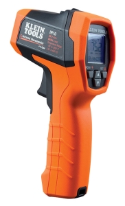
The CBM Infrared thermometer with type K input offers dual-mode temperature measurement (-40 to 650°C range, 20:1 optical resolution) with adjustable emissivity—critical when measuring refrigerant lines with varying surface finishes. The IP54 rating and 3-meter drop protection make it field-ready for Singapore's humid job sites.
Section 2: Step-by-Step Refrigerant Charge Verification Procedure
Pre-Measurement Preparation
Step 1: System Stabilization – Run the system for 15-20 minutes under normal operating conditions. Ensure evaporator airflow is steady and condenser fan operates normally. Measure ambient temperature; optimal verification occurs within 65–85°F (18–29°C) outdoor conditions—challenging during Singapore's peak heat but essential for accuracy.
Step 2: Instrument Calibration – Verify all gauges and thermometers have current calibration certificates. Measurement & Detection accuracy depends entirely on instrument reliability. Before each job, confirm manifold gauge accuracy by comparing readings on the same system over consecutive days.
Step 3: Safety Verification – Ensure all system access ports have proper valve configurations. Attach recovery cylinders and verify proper hose orientation. Use the Dwyer Pressure switch DXW-11-153-4 to confirm system pressures remain within safe operating windows (0.41–0.55 bar setpoint) before opening refrigerant lines.
Subcooling Measurement Process
Step 1: Measure Condenser Outlet Pressure – Connect your manifold gauge high-side port to the liquid-line service port. Record the pressure reading (this is your saturation point reference).
Step 2: Measure Liquid-Line Temperature – Using the CBM infrared thermometer, measure the temperature of the liquid line at the condenser outlet (closest point to where pressure was measured). Set emissivity to 0.95 for copper tubing. Take three readings and average them.
Step 3: Calculate Saturation Temperature – Reference your refrigerant saturation tables or manifold gauge digital display to find the saturation temperature corresponding to your measured pressure. Most modern manifold gauges display this automatically.
Step 4: Determine Subcooling – Subtract the measured liquid-line temperature from the saturation temperature. Typical target subcooling is 10–20°F (5.5–11°C) depending on system design. Values below 5°F suggest undercharge; values above 20°F suggest overcharge or restricted airflow.
Superheat Measurement Process
Step 1: Measure Evaporator Outlet Pressure – Connect your manifold gauge low-side port to the suction-line service port at the evaporator outlet. Record the pressure.
Step 2: Measure Suction-Line Temperature – Using your infrared thermometer, measure the suction-line temperature 6–12 inches from the evaporator outlet (avoid compressor suction lines). Take multiple readings for consistency.
Step 3: Calculate Saturation Temperature – Reference saturation tables for your refrigerant at the measured suction pressure.
Step 4: Determine Superheat – Subtract saturation temperature from measured suction-line temperature. Typical superheat targets range 8–15°F (4.4–8.3°C) for TXV systems and 15–25°F (8.3–13.9°C) for fixed-orifice systems. Superheat below 5°F indicates undercharge or TXV malfunction; superheat exceeding 25°F suggests significant undercharge or airflow restriction.
Integrating Flow Measurement for System Verification
After charge verification, confirm airflow meets design specifications using the Dwyer Medium flow metal probe MAFS-20. This 71 cm probe with 1/4-20 thread connection integrates into ductwork to measure actual flow rates. Compare measured flow against equipment specifications—restricted airflow causes false superheat readings that mask undercharge conditions.
Section 3: Pressure Monitoring and System Diagnostics
Real-Time Pressure Monitoring During Operation
For critical installations or problem diagnostics, install permanent pressure monitoring using the Dwyer Transmitter 629-05-CH-P2-E5-S1. This 4-20 mA pressure transmitter delivers 0.5% accuracy across 0–100 psid with IP65 protection. Mount it on both high and low-pressure lines to create a continuous Measurement & Detection baseline.
This transmitter integrates with building management systems (BMS) in Singapore commercial installations, providing:
- Real-time pressure trending to detect slow leaks
- Automated alerts when pressures drift beyond normal operating windows
- Historical data for capacity verification and equipment condition assessment
- Predictive maintenance triggers when pressure relationships deviate from baseline
Diagnostic Pressure Interpretation
High Suction Pressure with Low Discharge Pressure – Suggests low charge, compressor wear, or TXV failure. Measurement & Detection reveals which by examining superheat. Excessive superheat confirms undercharge; normal superheat with pressure anomaly indicates mechanical failure.
High Discharge Pressure with Normal Suction Pressure – Points to condenser fouling, improper charge, or non-condensable gases. Measure subcooling; excessive subcooling confirms overcharge.
Fluctuating Pressures During Stable Operating Conditions – Indicates TXV hunting, refrigerant maldistribution, or impending component failure. Document pressure variations over 5–10 minute cycles for trend analysis.
Pressure Switch Integration for Safety Monitoring
The Dwyer Pressure switch DXW-11-153-4 provides automated Measurement & Detection of critical pressure conditions. Install high-pressure cutout switches to prevent compressor damage from overcharge or condenser fouling. Low-pressure switches protect against evaporator freeze-up from undercharge or airflow loss.
Configure setpoints based on your specific equipment ratings and refrigerant type. In Singapore installations, account for outdoor temperatures exceeding 35°C—this elevates normal discharge pressures 15–25% above typical ratings.
Section 4: Documentation, Troubleshooting, and Best Practices
Creating Measurement & Detection Records
Document every charge verification on standardized forms including:
- Outdoor/indoor ambient temperatures at measurement time
- System operating time before measurement
- All pressure readings (high-side, low-side, at measured points)
- All temperature readings (liquid-line, suction-line, ambient, using specific instruments and locations)
- Calculated subcooling and superheat values
- Equipment nameplate data (refrigerant type, charge capacity, TXV setting if applicable)
- Airflow verification results
- Any adjustments made and the reason
- Contractor name, date, and system serial number
These records become invaluable when troubleshooting repeat service calls and defending warranty claims.
Common Charge Verification Mistakes and Solutions
Mistake: Measuring Temperature on Insulated Lines – Insulation prevents accurate infrared measurement. Solution: Remove insulation temporarily at measurement points, measure, then reinstall.
Mistake: Taking Measurements Under Transient Conditions – Charge verification requires stable pressures and temperatures. Solution: Allow 20–30 minutes of continuous operation in steady-state conditions (constant indoor/outdoor temperatures, stable compressor cycles).
Mistake: Ignoring Compressor Suction-Line Temperature – Compressor body heat raises suction-line temperature near the unit. Solution: Always measure suction temperature 6–12 inches from the evaporator outlet, never at the compressor inlet.
Mistake: Applying Standard Targets to All Systems – Superheat and subcooling targets vary by equipment design. Solution: Reference manufacturer specifications for your specific equipment; use 10–15°F as conservative defaults only when documentation is unavailable.
Troubleshooting with Measurement & Detection Data
When a system underperforms, your measurement data tells the story:
Low Cooling Capacity + High Superheat + Normal Subcooling → Likely undercharge; add refrigerant in small increments (0.25 lb) and remeasure after 15-minute stabilization.
Low Cooling + Normal Superheat + High Subcooling → Likely overcharge; recover refrigerant and measure again. Overcharge is more common after previous contractor "top-ups."
Normal Pressures + High Superheat + Normal Subcooling + Low Airflow → Evaporator airflow restriction (dirty filter, blocked ductwork, closed damper); Measurement & Detection eliminates false refrigerant diagnostics.
Fluctuating Pressures + Cycling Superheat + Normal Charge Readings → TXV malfunction or expansion device hunting; replace rather than adjust charge.
Measurement & Detection Best Practices for Singapore Operations
1. Account for Tropical Conditions – Singapore's humidity and heat elevate baseline pressures. Always benchmark against the specific system's design conditions, not generic industry standards.
2. Use Calibrated Instruments Only – Conduct annual gauge calibration services. A 2% error in pressure reading translates to ~5°F error in calculated temperatures—enough to hide serious problems.
3. Measure During Peak Load – Morning and evening temperatures in Singapore differ significantly. Always verify charge during the thermal load conditions the system will face (typically afternoon peak).
4. Document Baseline Data on New Installations – Take comprehensive measurements immediately after startup and retention. This baseline prevents disputes and enables future diagnostics.
5. Integrate Multiple Detection Methods – Never rely on subcooling or superheat alone. Cross-reference with pressure switch readings, flow measurements, and visual compressor operation.
6. Train Your Team on Instrument Use – The best tools yield poor results in untrained hands. Invest in technician certification on your specific manifold gauge and infrared thermometer models.
Conclusion: Measurement & Detection as Competitive Advantage
In Singapore's competitive HVAC market, precise Measurement & Detection of refrigerant charge separates contractors who build customer loyalty from those managing endless warranty callbacks. Systems verified with proper procedures and documented with detailed measurements run reliably, efficiently, and profitably.
3G Electric supplies the measurement instruments you need—from infrared thermometers and pressure transmitters to flow probes and pressure switches—with 35+ years of experience serving HVAC professionals across Southeast Asia. When you document your charge verification procedures with quality instruments from 3G Electric, you're investing in system reliability and your professional reputation.
Begin with your next installation: measure, document, and establish a baseline. Your future service calls will thank you.