Understanding Measurement & Detection System Integration Challenges
Measurement & Detection systems in modern industrial facilities rarely operate in isolation. Maintenance teams typically manage integrated networks combining temperature sensors, pressure gauges, gas detection centers, and electrical measurement devices that must communicate seamlessly. When these systems conflict—showing discrepancies between sensors monitoring the same parameter—productivity suffers and safety becomes compromised.
With over 35 years of experience distributing industrial equipment globally, 3G Electric has supported countless maintenance teams through these integration nightmares. The core issue isn't usually individual equipment failure; it's how multiple measurement and detection instruments interact within your system architecture.
This troubleshooting guide focuses on the practical reality maintenance teams face: diagnosing why your Measurement & Detection ecosystem produces inconsistent readings, identifying which sensors are reliable, and implementing systematic fixes that restore confidence in your monitoring infrastructure.
Systematic Diagnosis: Isolating Measurement & Detection Conflicts
Step 1: Document the Complete Sensor Network
Before troubleshooting, you must understand what you're actually monitoring. Create a detailed inventory including:
- Physical location of each measurement and detection device
- Sensor type and model (pressure, temperature, gas, electrical)
- Measurement range and accuracy specifications
- Installation date and last calibration date
- Communication protocol (analog, digital, wireless, hardwired)
- Power supply method and voltage rating
This documentation reveals patterns. Conflicts often cluster around sensors installed during the same project phase or those sharing power infrastructure.
Step 2: Perform Simultaneous Readings at Reference Points
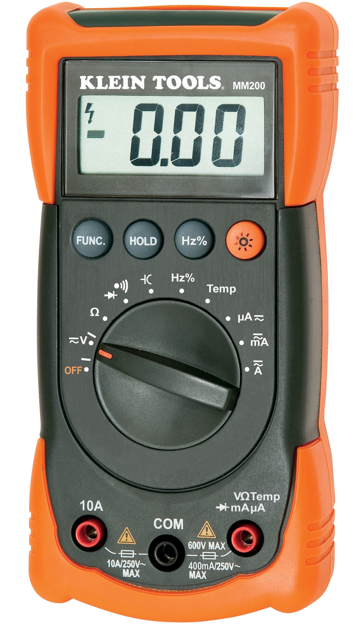
When temperature sensors report different values for the same location, or pressure gauges show 15-20% variance, you need independent verification. Use the CBM Automatic Multimeter MM420 as a neutral reference instrument:
- Take voltage measurements at each sensor's power input
- Verify signal output at each device's transmission point
- Document environmental conditions during measurement (ambient temperature, humidity, vibration)
- Compare readings taken consecutively within 60-second intervals
Discrepancies here reveal whether the problem is environmental drift, power instability, or genuine sensor degradation.
Step 3: Evaluate Environmental Factors Affecting Measurement & Detection Accuracy
Measurement & Detection systems are sensitive to installation context. Common environmental interference includes:
Temperature sensor conflicts often stem from proximity to heat sources. A surface temperature sensor like the CBM TE-SNW-E installed too close to steam lines, electrical terminals, or direct sunlight will consistently read higher than ambient readings. Verify mounting distance (minimum 300mm from radiant heat) and check for obstructions affecting air circulation.
Pressure gauge inconsistencies frequently involve mounting orientation. The CBM Green ABS pressure gauge D63 (0/+1bar G1/4) and D50 (0/+250bar G1/4) models require vertical installation with the gauge face pointing downward at 45-90 degrees. Horizontal or inverted mounting causes measurement drift.
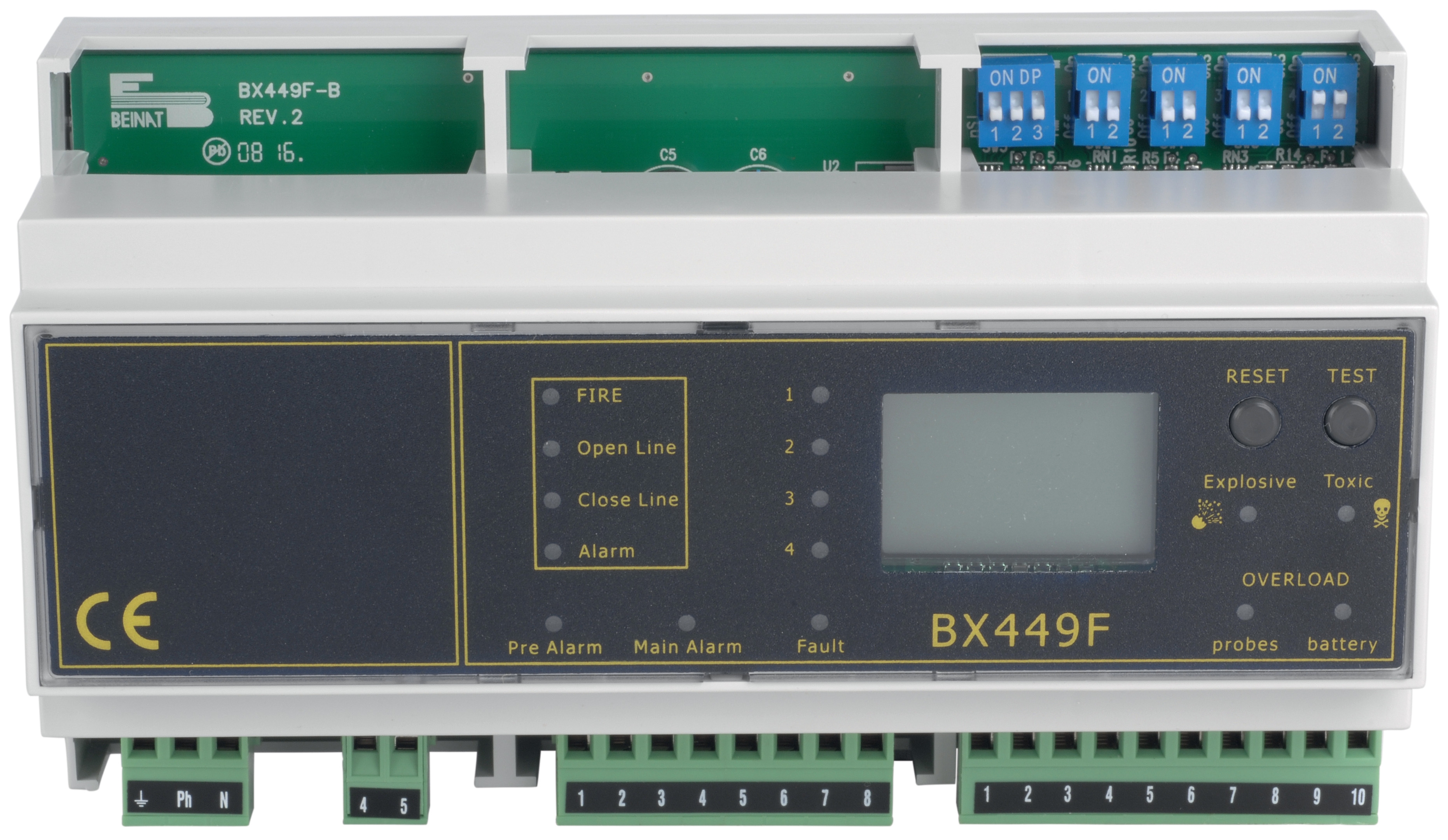
Gas detection center conflicts like the CBM Gas Detection Center Din Rail 8 Probes (12V) experience drift when probe locations don't account for gas flow patterns. Heavy gases settle low; lighter gases rise. Probe placement must match your facility's ventilation design.
Step 4: Check Signal Transmission and Integration Points
In networked Measurement & Detection systems, signal degradation occurs at connection points:
- Connector corrosion: Inspect all terminals and connectors for oxidation. Clean with dielectric grease and verify continuity.
- Cable integrity: Test cable resistance using your multimeter. Damaged shielding causes signal interference between sensors.
- Repeater/converter failures: If your system uses signal converters (analog-to-digital, wireless repeaters), test them independently with known-good input signals.
- Software/firmware synchronization: Verify all networked devices are running current firmware versions. Version mismatches cause data timing conflicts.
Practical Resolution: Restoring Measurement & Detection Consistency
Priority 1: Establish a Calibration Baseline
You cannot fix conflicts without knowing which sensor is actually correct. Implement this protocol:
1. Select your most critical measurement and detection point
2. Temporarily install a certified reference instrument (laboratory-grade for comparison)
3. Take 10 readings from each existing sensor at 5-minute intervals
4. Calculate mean, standard deviation, and accuracy variance for each
5. Compare against your reference instrument's readings
This identifies which sensors are trustworthy and which are drifting. Focus repair efforts on the outliers.
Priority 2: Isolate and Test Individual Systems
Disconnect sensors from the integrated network one at a time:
- Test each device independently with known input signals
- Verify power supply voltage matches specifications (use the MM420 multimeter for precise voltage verification)
- Check for output signal stability over 15-minute periods
- For gas detection systems like the CBM 8-probe center, test each probe individually before re-integration
This isolation process identifies whether the problem is the sensor itself or the integration architecture.
Priority 3: Recalibrate in Sequence
Don't recalibrate everything simultaneously. Follow this sequence:
1. Temperature sensors first: Verify the TE-SNW-E and comparable units against reference temperatures in ice bath (0°C) and warm water (37-40°C)
2. Pressure gauges second: Use D63 0/+1bar and D50 0/+250bar models according to their rated ranges with known test pressures
3. Electrical measurements last: Verify multimeter MM420 against known voltage/current sources
4. Gas detection integration final: Test the Din Rail 8-probe center probe channels sequentially with calibration gas
Sequential calibration prevents cascade failures where one bad sensor throws off others.
Priority 4: Implement Hardware Upgrades if Necessary
Some conflicts cannot be resolved through troubleshooting alone. Consider upgrading:
- Aged analog sensors to modern digital equivalents with built-in signal stabilization
- Single-point pressure gauges to redundant systems (dual CBM gauges provides verification capability)
- Older temperature sensors to intelligent units like the TE-SNW-E offering both local display and networked output
- Simple gas detection to centralized monitoring like the CBM 8-probe detection center enabling coordinated multi-point safety
Preventive Maintenance: Sustaining Measurement & Detection Reliability
Once integrated systems are functioning consistently, establish ongoing protocols:
Monthly verification: Compare readings from paired sensors monitoring the same parameter. Variance greater than ±5% indicates recalibration need.
Quarterly environmental audit: Verify sensor mounting conditions haven't changed. Check for new heat sources, vibration sources, or interference that could degrade Measurement & Detection accuracy.
Annual calibration: All sensors should be professionally calibrated annually, with records maintained. The MM420 multimeter itself should be verified against certified standards.
Software/firmware updates: For networked systems, maintain a regular update schedule. Schedule updates during low-risk windows to avoid measurement gaps.
Documentation maintenance: Keep your sensor inventory updated with calibration dates, readings history, and any modifications. Patterns in this data reveal degradation before failures occur.
Global Considerations for Measurement & Detection Systems
Maintenance teams operating across multiple regions should account for:
Regulatory differences: Gas detection requirements vary significantly (US EPA vs. EU ATEX standards). Ensure your detection center and probe configurations comply with local regulations.
Environmental variations: Temperature sensors and pressure gauges experience different drift patterns in tropical versus arctic climates. Establish region-specific calibration frequencies.
Supply chain resilience: Maintain spare sensors for critical measurement and detection points. 3G Electric's global distribution network ensures rapid replacement availability when failures occur.
Training consistency: Measurement & Detection troubleshooting requires trained personnel. Ensure maintenance team members across locations follow identical diagnostic protocols.
Conclusion: Building Confidence in Your Measurement & Detection Systems
Integrated Measurement & Detection systems provide invaluable visibility into facility operations—but only when data is trustworthy. By systematically diagnosing conflicts, establishing baselines, isolating failures, and implementing preventive maintenance, maintenance teams restore confidence that their sensors accurately reflect reality.
3G Electric's 35+ years supporting global industrial facilities demonstrates that measurement and detection challenges are universal, but solutions are achievable through methodical troubleshooting. Apply these procedures, maintain detailed records, and your integrated monitoring systems become the reliable foundation for safe, efficient operations.