Introduction: Why Measurement & Detection Matters for Chilled Water Systems
Chilled water systems are the backbone of commercial HVAC in Singapore's tropical climate. These systems require precise Measurement & Detection at multiple points to maintain efficiency, prevent failures, and ensure occupant comfort. Whether you're commissioning a new system, troubleshooting performance issues, or performing routine maintenance, accurate measurement tools are non-negotiable.
At 3G Electric, we've supported HVAC contractors across Southeast Asia for over 35 years, helping them select the right instrumentation for their specific applications. This guide focuses on the practical measurement and detection techniques that keep chilled water systems performing reliably in Singapore's high-temperature, high-humidity environment.
Section 1: Pressure Measurement at Supply and Return Points
Why Pressure Measurement is Critical
Pressure differential across chilled water coils indicates system health. Low pressure can signal fouling, blockages, or pump failure. Excessive pressure suggests oversizing, control valve issues, or distribution line problems. By taking pressure readings at supply and return points, you establish a baseline for normal operation and detect deviations early.
In Singapore's 24/7 cooling demand, pressure variations often precede system failures by hours or days—giving you time to intervene before downtime occurs.
Installation Points
Install pressure measurement taps at:
- Chiller outlet (supply header)
- Coil inlet on main distribution loops
- Return header before chiller inlet
- Individual branch circuit inlets (for balancing)
For vertical installations and clear readability on site, use the Preciman Manometer ABS vert D80 0/+16bar G1/2. This glycerin-filled gauge provides ±2.5% accuracy and handles vibration well in mechanical rooms. The 80 mm dial is large enough for quick field readings, and the 0–16 bar range covers typical chilled water pressures (2–7 bar for most systems).
Reading and Recording Pressure
- Record baseline pressures during commissioning at design flow rates
- Check readings weekly during commissioning phase, monthly thereafter
- Compare coil pressure drop to design specifications—increases above 10% warrant coil cleaning
- Track return pressure trends; rising return pressure with stable supply pressure indicates blockage downstream
Document all readings in your maintenance log. Over 3–6 months, you'll identify normal seasonal variation and spot abnormal trends immediately.
Section 2: Temperature Detection for Coil Performance Verification
Critical Temperature Measurement Points
Temperature measurement at four points reveals coil performance and system balance:
1. Chiller outlet – Design setpoint (typically 6–7°C in Singapore)
2. Coil inlet – Should match chiller outlet minus minor distribution loss (~0.5°C)
3. Coil outlet – Determines cooling delivered to space
4. Return water temperature – Shows load and return path condition
Using Infrared Detection for Rapid Assessment
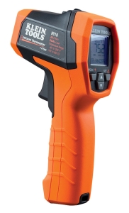
For quick field diagnostics, the CBM Infrared thermometer with type K input lets you measure surface temperatures on pipes without breaking connections. Measure:
- Supply pipe surface 1 meter from chiller outlet
- Return pipe surface before chiller inlet
- Coil outlet connections
The 20:1 optical resolution (0.5 m distance measurement at 20:1 ratio) allows accurate readings from 3 meters away—useful when access is limited. The adjustable emissivity (0.10–1.00) adapts to different pipe materials (steel, copper, insulation).
Temperature analysis:
- Supply–return differential of 4–6°C indicates balanced load distribution
- Less than 3°C difference suggests insufficient flow or pump cavitation
- More than 8°C indicates over-concentration of load on fewer coils
- Coil outlet warmer than design by >2°C means fouling or undersized coil
The CBM's IP54 rating and 3 m drop protection suit Singapore's humid mechanical rooms where condensation and occasional equipment drops are realities.
Section 3: Flow Rate Measurement and System Balance
Understanding Flow Detection in Chilled Water Systems
Flow rate measurement confirms whether your distribution system delivers design flow to all coils. Under-flow zones create "dead legs" where water stagnates; over-flow creates pressure problems. Proper flow detection catches these issues during commissioning.
Installing Flow Measurement Probes
Use the Dwyer Medium flow metal probe MAFS-20 in main distribution headers and branch circuits. The 71 cm probe length accommodates most standard ductile iron or copper headers. The 1/4-20 thread connection fits standard tapping points.
Installation procedure:
1. Locate main supply header; mark measurement point 2–3 pipe diameters downstream of pump discharge (allows flow profile stabilization)
2. Install isolation ball valve upstream of tapping point
3. Thread the MAFS-20 probe into tapping; insert approximately 10–15 cm into pipe centerline
4. Connect differential pressure transmitter or manometer to probe tap
5. Take reading at design flow conditions; record as baseline
Flow Balancing Workflow
- Measure supply header flow first—should match design (typically 0.8–1.2 m/s velocity)
- Measure each branch circuit inlet; sum should approximately equal main header flow
- Adjust balance valves on low-flow branches to increase resistance on over-flowing circuits
- Rebalance until all coils receive ±10% of design flow
- Measure return flows to confirm closure
In Singapore's multi-zone buildings, proper flow balance is essential because uneven distribution causes thermal comfort complaints and shortens coil life.
Section 4: Pressure Switch and Transmitter Integration for Continuous Detection
Why Continuous Monitoring Matters
Manual measurement tells you when you check. Continuous monitoring tells you if something changes. Install pressure switches and transmitters for automated fault detection and trending.
Pressure Switch Installation
Use the Dwyer Pressure switch DXW-11-153-4 on chiller outlet to detect low-pressure conditions (fouling, cavitation). This switch triggers an alarm or log event when pressure falls below setpoint (0.41–0.55 bar range, adjustable). The 3.46–5.17 bar differential range prevents nuisance alarms from normal cycling.
Installation:
- Install isolation valve and snubber (damping device) upstream of switch
- Set alarm threshold 0.5 bar below minimum expected operating pressure
- Connect 24 VDC control circuit to building management system (BMS)
- Test quarterly to ensure electrical contacts function
The IP65 protection suits humid mechanical rooms; the 5 A @ 125/250 VAC rating handles direct switching of indicator lights and solenoid valves.
Pressure Transmitter for Trending
For comprehensive data logging, install the Dwyer Transmitter 629-05-CH-P2-E5-S1 on both supply and return headers. This 4-20 mA output device sends real-time pressure data to your BMS, enabling:
- Historical trend analysis
- Automatic pressure drop calculation across coils
- Predictive maintenance alerts (pressure rising = fouling, pressure dropping = flow issue)
- Remote monitoring from off-site
- 0–100 psid (0–6.9 bar) range covers typical system pressures
- 0.5% accuracy ensures reliable trending
- NPT 1/4" connection standard on most headers
- IP65 rating protects electronics in wet environments
The 4-20 mA signal integrates with any building automation platform. Connect to BMS with shielded twisted-pair cabling; include surge protection given Singapore's thunderstorm exposure.
Practical Commissioning Sequence for HVAC Contractors
Day 1 – Initial Measurement Setup:
1. Install pressure taps at all critical points; cap unused taps
2. Mount manometers (Preciman units) on visible board in mechanical room
3. Install flow probe in main supply header
4. Install infrared thermometer in technician toolkit
Day 2 – Baseline Documentation:
1. Start pump at design speed; record all manometer readings
2. Measure coil temperatures with infrared; document surface temps
3. Measure main flow with MAFS-20 probe; calculate velocity
4. Take digital photos of all gauges with readings visible
Day 3–5 – Balance and Commissioning:
1. Adjust balance valves on branch circuits; recheck flow distribution
2. Verify pressure differentials match design calculations
3. Confirm supply–return temperature profile
4. Install pressure switches and transmitters; calibrate setpoints
Week 2 – Handover and Documentation:
1. Train building operations staff on gauge readings
2. Provide baseline data sheet with photos and setpoints
3. Schedule first post-commissioning check (24 hours)
4. Document all settings in operations manual
Section 5: Troubleshooting Common Chilled Water Problems Using Measurement Data
Scenario 1: Rising Coil Pressure Drop
Symptom: Pressure differential across coil increasing week-over-week; return temperature rising
Detection method: Compare current manometer reading to baseline; use infrared to spot temperature imbalance
Action:
- Coil fouling suspected—schedule water treatment and coil cleaning
- Increase monitoring frequency to daily until cleaned
- Adjust setpoint on pressure switch upward temporarily to prevent false alarms
Scenario 2: Uneven Temperature Across Distribution
Symptom: Some zones reporting comfort complaints; infrared readings show branch lines at different temperatures
Detection method: Infrared scan of all branch circuit pipes; check MAFS-20 flow readings on each
Action:
- Low-temperature branches are over-fed; adjust balance valve
- High-temperature branches are under-fed; open balance valve
- Rebalance systematically; recheck infrared temps every 15 minutes
Scenario 3: Pump Not Delivering Design Pressure
Symptom: Manometer reads 1.5 bar instead of expected 3.0 bar; system struggling to cool
Detection method: Check pump discharge pressure; flow probe reading
Action:
- If flow is zero, pump cavitating—check suction line for blockage, priming issues
- If flow is normal but pressure low, pump impeller worn—schedule replacement
- If flow and pressure both low, system air-bound—bleed air vents manually
Maintenance Schedule for Measurement Instruments
Monthly:
- Visual inspection of manometers for glycerin clarity; refill if discolored
- Check pressure switch housing for corrosion or water ingress
- Verify transmitter LED indicator illuminated (power present)
- Pressure test switches (manually trigger to verify contacts)
- Calibration check on infrared thermometer against known reference
- Clean probe windows on infrared device
- Professional calibration of pressure transmitters (±0.5% verification)
- Manometer certification (if required by facility standards)
- Replace any glycerin if degradation visible
Over 35 years, 3G Electric has seen measurement instruments outlast the systems they monitor when maintained properly. A $200 investment in annual calibration prevents thousands in misdiagnosis and downtime.
Conclusion: Building a Measurement & Detection Culture
Accurate Measurement & Detection transforms HVAC maintenance from reactive to predictive. By installing the right instruments, taking baseline readings, and monitoring trends, you shift from "fixing problems when they fail" to "fixing problems before they start."
Singapore's competitive commercial real estate market rewards contractors who deliver reliable comfort with minimal emergency calls. Clients notice when their systems run smoothly, and that reputation attracts new work.
Start with pressure and temperature measurement on your next chilled water commissioning. Use the Preciman manometer for baseline readings, the CBM infrared thermometer for rapid diagnostics, the Dwyer flow probe for balancing, and the Dwyer pressure switch and transmitter for ongoing monitoring. Within one year, you'll have enough trend data to anticipate maintenance needs 4–6 weeks in advance.
That's the practical difference between managing systems and truly understanding them.