Maintenance & Service in Multi-Pump Industrial Operations
When your plant operates multiple high-pressure pumps—whether in cascade configurations, parallel feed systems, or redundant backup arrangements—Maintenance & Service shifts from individual component care to system-wide coordination. With over 35 years of experience distributing industrial equipment across Asia-Pacific, 3G Electric has supported hundreds of Singapore plants through the operational complexities of managing interconnected pump networks. The challenge isn't just maintaining each pump; it's understanding how failures in one unit cascade through your entire system.
Multi-pump installations are increasingly common in Singapore's industrial sector—from large-scale HVAC systems to high-pressure fluid transfer operations. Unlike single-pump systems where downtime affects one process line, a coordinated multi-pump failure can halt production across multiple zones simultaneously. This article addresses the practical maintenance strategies that prevent that scenario.
Section 1: Integrated System Monitoring and Diagnostic Protocols
Establishing Baseline Performance Metrics
Before you can identify problems, you need to know what "normal" looks like for your specific installation. Each pump in your network will have slightly different operating characteristics based on:
- Flow rate stability across different load conditions
- Pressure readings at inlet, outlet, and critical junction points
- Temperature patterns during peak and idle periods
- Vibration signatures that indicate bearing wear or imbalance
- Acoustic profiles that reveal cavitation, aeration, or seal degradation
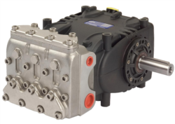
For example, the Pratissoli KF30 pump operates at 200 bar and 106 L/min under full load—but your baseline should capture how it performs at 75% load, 50% load, and standby. Temperature variance, pressure ripple, and noise changes at these different points become your early warning system.
Document these baselines during the first 500 operating hours after installation. Assign one technician the responsibility of recording readings at consistent intervals—ideally every two weeks for the first three months, then monthly thereafter. This data becomes invaluable when troubleshooting anomalies.
Multi-Point Pressure Monitoring Systems
In a multi-pump configuration, pressure readings at different locations tell you which unit is underperforming:
- Pump discharge pressure: Reveals if the pump itself is losing efficiency
- System supply header pressure: Shows overall network health
- Individual branch pressures: Identifies load imbalances or blockages
- Return line back-pressure: Indicates filter saturation or cooler fouling
Install pressure gauges—or better, pressure transducers with digital logging—at these critical points. For systems using the Interpump PUMP W2035 L ATEX, which delivers 35 L/min at 200 bar with ATEX compliance for hazardous environments, monitor the discharge pressure continuously. A gradual decline from 200 bar to 195 bar over weeks suggests internal leakage; a sudden drop indicates seal failure or cavitation.
Thermal Monitoring as a Preventive Indicator
Pump fluid temperature is your most underutilized diagnostic tool. High-pressure pumps generate heat through internal friction and leakage. When temperature climbs unexpectedly:
- 5-10°C increase: Minor efficiency loss, typically from cavitation or aeration
- 10-15°C increase: Significant wear, possible seal degradation
- >15°C increase: Severe problem—stop operations and inspect immediately
Install fluid temperature sensors in the return line where they measure bulk system temperature. Thermal imaging cameras can also reveal hot spots on pump housings that indicate localized internal problems. Many Singapore plants neglect this until catastrophic failure occurs; systematic thermal monitoring prevents that outcome.
Section 2: Scheduled Service Protocols for Multi-Pump Networks
Staggered Maintenance Windows
The cardinal rule: never service all pumps simultaneously. Even if you have redundancy, simultaneous maintenance creates a single point of failure window.
For a three-pump installation, your staggered schedule might look like:
- Week 1: Inspect and service Pump A (visual inspection, seal check, fluid sampling)
- Week 3: Inspect and service Pump B
- Week 5: Inspect and service Pump C
- Week 7: Detailed fluid analysis from all three units
- Week 8-10: Gearbox inspection (if using units like the Interpump GEARBOX RS500 D. 1" gearbox with 2.2 transmission ratio)
This rotation ensures at least two operational pumps at any time. Document each service session—what was inspected, what was cleaned, any parts replaced, any anomalies noted. This creates your maintenance history, which is essential for predicting failures.
Fluid Analysis: The Early Warning System
Fluid condition tells you everything about pump health. Every 250-500 operating hours, collect fluid samples from the return line and send them for laboratory analysis (most Singapore industrial areas have ISO 4406-certified labs). The analysis should measure:
- Particle count (ISO 4406 coding: 18/16/13 or better is typical)
- Water content (target: <500 ppm)
- Viscosity stability (compare to fresh fluid specifications)
- Acid number (TAN—indicates oxidation and contamination)
- Ferrous particle concentration (indicates internal wear)
A sudden spike in ferrous particles suggests bearing wear; an increase in non-ferrous particles indicates pump housing or seal degradation. Water ingress points to seal failure or condensation problems. This data lets you schedule component replacement before failure cascades through your system.
Component-Specific Service Intervals
For the Pratissoli SN7045 L pump operating at 210 bar and 1450 rpm:
- Filters: Replace every 500 hours or when pressure differential exceeds 3.5 bar
- Seals: Inspect every 1000 hours; replace at 2000 hours or at first sign of leakage
- Bearings: Thermal imaging and vibration analysis at 1500-hour intervals; replace at 3000-4000 hours depending on load profile
- Coupling alignment: Check laser-aligned every 250 operating hours (misalignment creates premature bearing wear)
For multi-pump systems, synchronize filter changes across all units. If you change one pump's filter but not another's, the unfiltered pump will contaminate the shared fluid loop, negating the benefit of the filter change.
Section 3: Failure Prevention Through Integration Awareness
Cross-Pump Load Balancing
In parallel pump configurations, unequal pressure drops between units cause some pumps to work harder than others. The harder-working pump ages faster, creating a cascading failure pattern:
1. Pump A degrades slightly, losing 2-3 bar efficiency
2. Pump B automatically compensates, exceeding design pressure by 5-8 bar
3. Pump B's seals fail after 60% of expected life
4. System pressure spikes, overloading Pump C
5. All three units fail within weeks
Prevent this by:
- Installing pressure relief valves set to exactly the same pressure on each pump's discharge
- Checking pressure at each pump's outlet monthly, not just at system header
- Installing individual flow meters on parallel lines to spot load imbalance immediately
- Adjusting pump displacement (if variable displacement units) or intake conditions to equalize load
ATEX-Compliant Systems and Hazardous Environment Maintenance
If your plant uses units like the Interpump PUMP W2035 L ATEX, which operates in hazardous (explosive) environments with ATEX certification, maintenance becomes more complex. The ATEX certification requires:
- Documentation of all maintenance activities (keep detailed records)
- Qualified personnel handling the unit (technicians must understand ATEX compliance)
- Spare parts sourced from authorized suppliers (not generic replacements)
- Testing certification after major repairs (third-party testing may be required)
For Singapore plants in petrochemical, refineries, or chemical processing, this means your maintenance protocol must include ATEX audits every 12 months. Non-compliance can result in facility shutdowns and liability issues.
Detection and Control System Integration
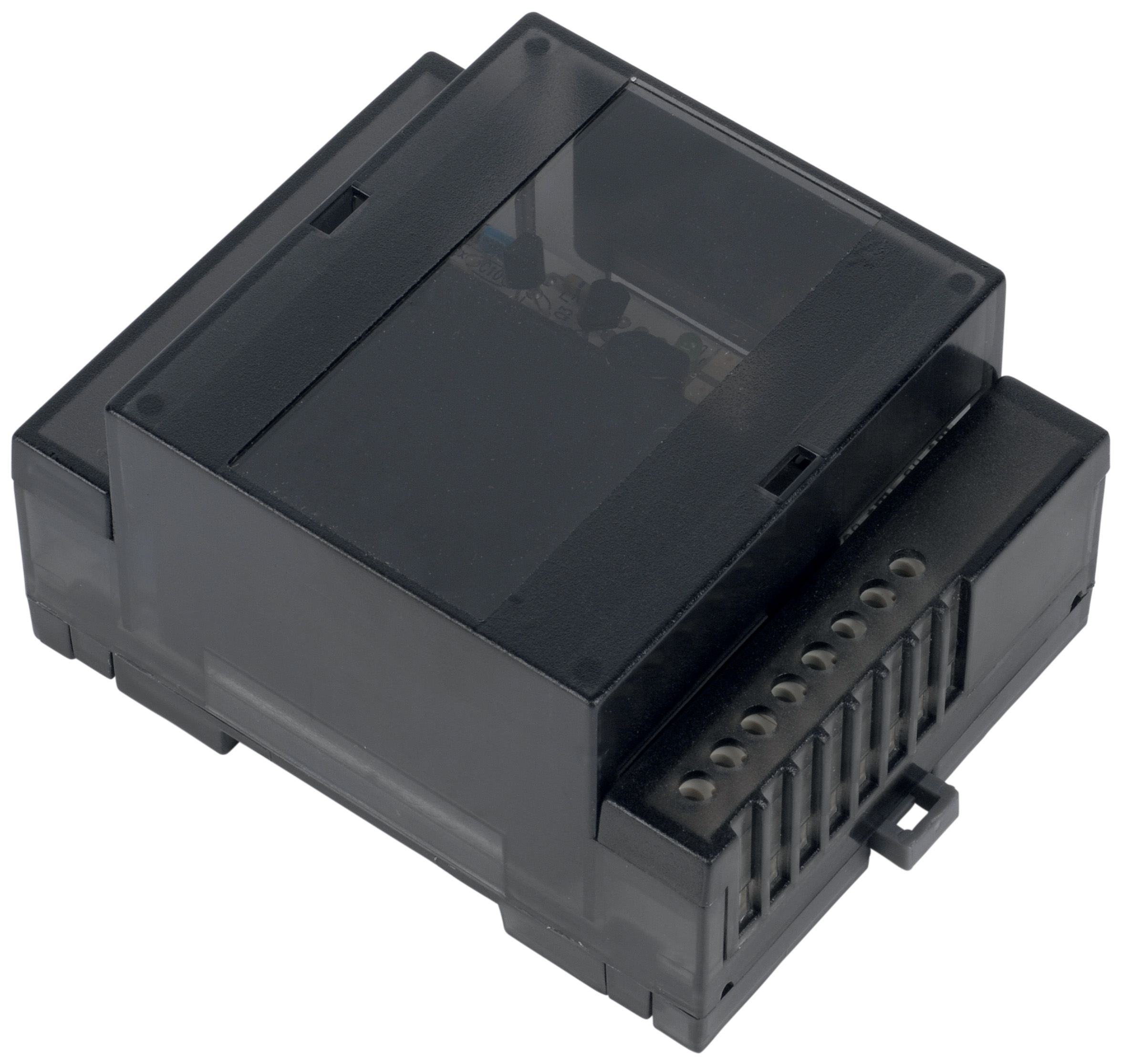
Multi-pump systems often integrate combustion control modules like the Combutech Flame relay CF1, which monitors system safety. This device supports up to 10 UV detectors and triggers safety shutdowns if anomalies occur.
Include detection system maintenance in your pump service protocol:
- Verify detector sensitivity every 500 hours (false shutdowns waste time; missed shutdowns create safety hazards)
- Clean UV lenses monthly (dust and debris reduce detection accuracy)
- Test relay response time quarterly (should trigger within 1 second of flame loss)
- Check wiring integrity during pump maintenance (corroded contacts cause false signals)
A malfunctioning flame relay might shut down your entire pump system, appearing as a mechanical failure when the real problem is electrical.
Section 4: Creating Your Site-Specific Maintenance Manual
Documentation Requirements
Your maintenance program lives or dies based on documentation. Create a site-specific manual that includes:
1. System Schematic
- Pump locations, model numbers, serial numbers
- Pressure test points and normal operating ranges
- Isolation valves and bypass routes
- Control system connections (especially for ATEX-certified units)
- Daily: Visual inspection log, temperature recording
- Weekly: Pressure readings, leak checks
- Monthly: Fluid sampling, thermal imaging, vibration baseline
- Quarterly: Seal inspection, coupling alignment check, detector testing
- Annually: Full system audit, ATEX compliance verification (if applicable)
- Pressure drops → check relief valve setting → check for internal leakage → check for cavitation
- Temperature rise → check filter saturation → check cooler fouling → check for aeration
- Noise/vibration → check coupling alignment → check bearing condition → check fluid aeration
- Seals (matched to specific pump models)
- Bearings (with replacement schedule)
- Filters (bulk purchase at 10% discount)
- Coupling elements
- Pressure relief cartridges
Many Singapore plants maintain $3,000-5,000 in spare parts inventory. When failure occurs at 2 AM, having seals and bearings on-site means 2-hour repairs instead of 2-day shutdowns.
Training and Knowledge Transfer
Your maintenance program is only as good as the technicians executing it. Establish:
- Initial training: New technicians spend one week shadowing experienced staff, learning your system's specific characteristics
- Quarterly training: Update the team on any system modifications, new equipment, or lessons learned from previous failures
- Cross-training: Ensure at least two technicians understand every critical system (one person cannot maintain everything)
- Documentation sign-off: Whoever performs maintenance must sign and date the service log; this creates accountability
With 35 years of experience supporting industrial operations across Singapore, 3G Electric can recommend technicians and training resources specific to your equipment brands and configurations.
Practical Implementation: 90-Day Launch Plan
Week 1-2: Establish baseline metrics
- Install all pressure, temperature, and vibration sensors
- Record baseline data from all pumps at various load levels
- Document current fluid condition (send sample for lab analysis)
- Service Pump A (inspect, clean, fluid change)
- Implement pressure relief valve synchronization if needed
- Verify detector/relay functionality
- Service Pumps B and C on staggered schedule
- Compile baseline data into comparison charts
- Identify any anomalies that require immediate attention
- Finalize site-specific maintenance manual
- Schedule monthly pressure/temperature monitoring
- Establish quarterly fluid sampling routine
- Create spare parts inventory purchasing schedule
By the end of 90 days, you'll have eliminated reactive maintenance and shifted to predictive protocols. The result: 20-30% longer equipment life, 40-50% reduction in emergency repairs, and zero unplanned shutdowns tied to pump failure.