How to Integrate High-Pressure Pumps with Gas Burner Systems: A Technical Guide for HVAC Contractors
When designing or upgrading industrial heating systems, HVAC contractors often encounter applications requiring both precision pressure control and reliable fuel delivery. Integrating high-pressure pumps with gas burner systems demands careful attention to component compatibility, pressure ratings, and installation methodology. This guide walks through the technical fundamentals of combining industrial pumps with modern gas burners, featuring real product specifications and practical installation procedures used by professionals in industrial facilities across the globe. Whether you're commissioning a new system or troubleshooting an existing installation, understanding pump-burner integration ensures optimal performance, safety, and longevity.
Understanding Pump-Burner System Architecture
High-pressure pump and gas burner integration represents a critical subsystem within modern industrial heating installations. At its core, this architecture serves two complementary functions: maintaining consistent fuel pressure delivery to the burner and enabling precise flame modulation through pressure-regulated flow control. Unlike standalone burner installations, integrated pump-burner systems require synchronization between pump output characteristics and burner input specifications.
The fundamental principle governing successful integration is pressure compatibility. Industrial burners operate within specific pressure windows—typically measured in millibar (mbar) or bar units—which ensure optimal combustion efficiency and flame stability. When a high-pressure pump operates upstream of a burner system, it must deliver fuel at the burner's designed inlet pressure while accounting for line losses, elevation changes, and system dynamics. Undersizing the pump results in insufficient pressure delivery and incomplete combustion; oversizing creates excessive back-pressure that can damage burner internals and waste energy.
A secondary consideration involves flow rate alignment. The pump's volumetric output (measured in liters per minute or US gallons per minute) must match the burner's fuel consumption rate under full-load operation. This relationship becomes increasingly important in systems using modulating burners, which require smooth pressure and flow variation across their operating range. The pump-burner pairing also influences overall system efficiency, response time to load changes, and component lifespan. Understanding these foundational principles prepares you for intelligent product selection and reliable installation.
Technical Specifications and Product Integration
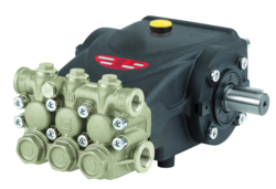
When specifying components for pump-burner integration, precise technical data drives decision-making. Consider the Interpump E3B2515I pump, a compact high-pressure unit designed for industrial applications. This pump delivers 15 liters per minute (3.96 US gallons per minute) at a maximum pressure of 250 bar (3,625 PSI), with a rated power output of 7.13 kilowatts (9.7 horsepower). Operating at 1,450 RPM, it maintains consistent volumetric displacement while remaining compact enough for space-constrained installations. The unit weighs approximately 9.5 kilograms and features overall dimensions of 265mm, making it suitable for wall-mounted or pedestal configurations.
Pairing this pump with an appropriately specified burner requires matching these performance metrics to burner design parameters. The FBR GASP X5/MCE burner represents a modern modulating gas burner with die-cast aluminum construction, high-efficiency combustion head, and integrated flame stability controls. This burner accommodates natural gas across multiple gas categories (I2R, I2H, I2L, I2E, I2E+, I2Er, I2ELL, and I3 series) with a minimum gas train pressure of 27-33 mbar. The burner's 370-watt fan motor operates at high pressurization, supporting power output ranging from 69.8 kW minimum to 349 kW maximum, with IP 40 electrical protection rating suitable for industrial environments.
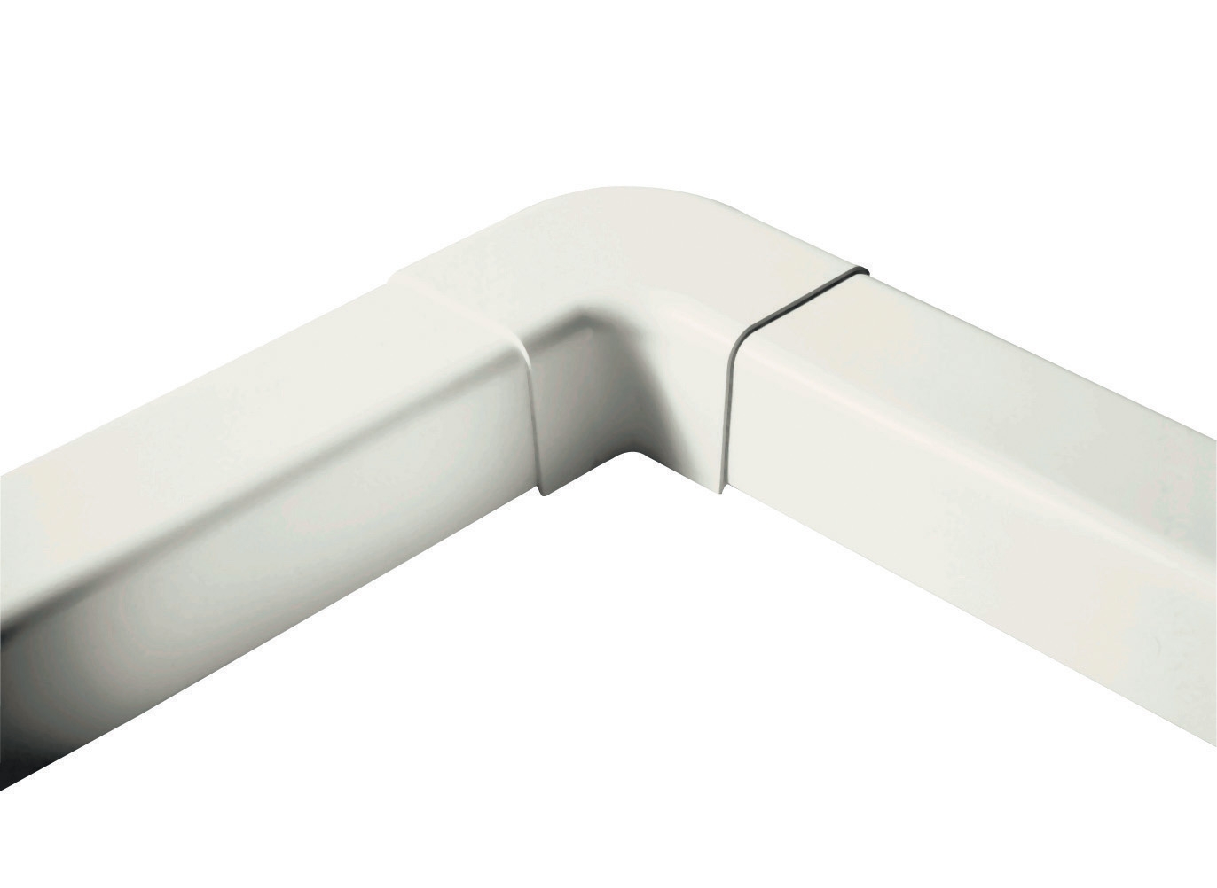
The integration challenge emerges when translating pump outlet pressure (250 bar) into burner inlet requirements (27-33 mbar). This extreme pressure differential necessitates a precision pressure regulator positioned immediately downstream of the pump. Additionally, the pump's 15 L/min flow capacity supports burner firing rates in the mid-to-upper industrial range, making this pairing suitable for facilities with moderate to high thermal loads. Complementary components like the CBM 90° flat elbow fitting (60mm) enable efficient piping layout and pressure-drop minimization. Selecting and installing these components correctly prevents common integration failures such as pressure spikes, flow starvation, and component incompatibility.
Step-by-Step Integration and Installation Procedure
Step 1: System Design and Pressure Mapping
Before installation begins, create a detailed system schematic identifying all components, their pressure ratings, and connection points. Calculate expected pressure drops across piping, fittings, and control devices using industry standard formulas or software tools. Verify that your selected pump outlet pressure (accounting for regulation) falls within the burner's acceptable inlet pressure range. Document minimum inlet pressure requirements, emergency shutdown pressure thresholds, and any safety relief settings mandated by local codes or manufacturer guidelines.
Step 2: Pump Mounting and Alignment
Install the pump on a stable, vibration-isolated mounting surface using appropriate brackets and fasteners rated for the pump's operational load. For wall-mounted configurations, use certified mounting hardware like adjustable wall brackets rated for 100+ kilograms. Ensure proper motor shaft alignment with any driven equipment or couplings, maintaining concentricity within manufacturer tolerances (typically ±0.05mm). Connect electrical power according to the pump motor specifications, verifying voltage and phase compatibility with facility supply.
Step 3: Piping and Component Installation
Connect the pump discharge to the pressure regulator using appropriately sized rigid or reinforced flexible tubing rated for the system's maximum pressure. Install isolation ball valves on both pump inlet and outlet to enable service without system drainage. Position pressure gauges at key points: pump discharge, regulator inlet, and burner inlet. These measurement points enable real-time system monitoring and troubleshooting. Install the burner downstream of the pressure regulator, ensuring all pipe connections are mechanically secure and leak-free.
Step 4: Testing and Commissioning
With the system assembled but not yet operational, conduct a static pressure test by pressurizing the system to 1.5 times the maximum working pressure and observing for 30 minutes without pressure decay. This confirms seal integrity and component quality. Once static testing passes, perform dynamic commissioning by gradually increasing pump speed while monitoring inlet and outlet pressures. Adjust the pressure regulator to achieve the burner's specified inlet pressure. Ignite the burner and observe flame characteristics, ensuring stable combustion across the burner's modulation range.
Selection Criteria and Best Practices
Selecting the optimal pump-burner combination requires evaluating several critical factors beyond basic specifications. Load Profile Analysis: Determine your facility's thermal demand range under normal, peak, and minimum operating conditions. A burner that operates consistently near its rated capacity delivers superior efficiency compared to one that fires at 20% capacity. If your load profile varies significantly, consider multi-burner systems or modulating burners paired with variable-displacement pumps.
Pressure Margin and Safety: Always specify a pump with maximum pressure rating at least 25% above the system's designed working pressure. This safety margin accommodates pressure spikes from rapid load changes or control valve actions. Verify that all system components—piping, fittings, gauges, and regulators—carry pressure ratings matching or exceeding this maximum. Component undersizing represents a frequent cause of system failures and safety incidents.
Maintenance Accessibility: Design your system layout to provide unobstructed access to the pump, regulator, gauges, and strainer for routine maintenance. Schedule annual inspection of pump seals, bearing condition, and electrical connections. Filter the fuel supply upstream of the pump using 100-micron screens, preventing particulate damage to high-precision pump internals. Monitor and replace filters per manufacturer recommendations, typically every 500-1,000 operating hours depending on fuel quality.
Environmental Considerations: Industrial environments subject pumps to vibration, temperature extremes, and corrosive atmospheres. Specify corrosion-resistant construction materials where applicable. In tropical climates or marine environments, use stainless steel fittings and consider protective coatings for external components. Ensure adequate ventilation around pump motor housings to prevent thermal degradation of electrical insulation, particularly important in high-ambient-temperature industrial facilities.
Common Integration Challenges and Solutions
Even experienced contractors encounter integration issues when combining disparate pump and burner products. Pressure Regulation Instability: If your system exhibits hunting (oscillating pressure), the regulator response time may be mismatched to the system's flow characteristics. Install a small accumulator (0.5-1.0 liter) between the pump discharge and regulator inlet to dampen pressure transients and improve control stability. Fuel Starvation During Modulation: When the burner modulates to minimum firing rate, insufficient pump flow may cause pressure collapse. Verify that your pump's displacement rating exceeds the burner's minimum fuel consumption rate by at least 20%, ensuring stable operation across the entire modulation range.
Excessive Pressure Drop in Piping: Long pipe runs or undersized tubing can create pressure drops exceeding the regulator's compensation capability. Calculate actual pressure drop using Darcy-Weisbach equations or hydraulic simulation software. If calculated drop exceeds 5% of system pressure, increase pipe diameter or reduce line length through system redesign. Remember that even small pipe size reductions (e.g., 10mm to 8mm) significantly increase flow resistance at higher flow rates.
Measurement and Monitoring Best Practices
Reliable system operation depends on accurate pressure measurement and monitoring. Install high-quality pressure gauges at critical points, using liquid-filled models like the CBM glycerin-filled stainless steel gauge (0-4 bar, G1/4 connection) for environments with vibration or pressure pulsation. The glycerin damping fluid prevents needle flutter, enabling accurate reading interpretation. Record baseline pressure measurements during commissioning and compare subsequent measurements to detect gradual performance degradation. Pressure increase over time suggests pump wear or strainer blockage; pressure decrease suggests regulator drift or internal leakage.
For systems requiring continuous monitoring or remote diagnostics, consider installing electronic pressure transducers connected to a building management system or data logger. This approach enables trend analysis, predictive maintenance scheduling, and rapid fault detection before system shutdown occurs.
Successful integration of high-pressure pumps with gas burner systems requires technical knowledge, quality components, and meticulous installation methodology. By following this guide's specifications and procedures, HVAC contractors can design and install systems delivering reliable performance across industrial applications worldwide. When component selection questions arise or installation support is needed, contact 3G Electric's technical team. As an experienced industrial equipment distributor serving global customers since 1990, we provide expert guidance on pump selection, burner integration, and complete system commissioning. Our experienced professionals can review your application requirements and recommend components optimized for your facility's specific demands. Reach out today to discuss your next pump-burner integration project.