Industrial Pump Pressure System Troubleshooting: Diagnostic Procedures for Global Applications
Industrial pump failures represent one of the most costly maintenance challenges in manufacturing and processing facilities worldwide. Pressure system malfunctions can lead to extended downtime, reduced production capacity, and cascading equipment damage if not diagnosed and resolved systematically. Procurement and maintenance engineers require a structured diagnostic framework that isolates root causes—whether mechanical wear, pressure loss, cavitation, or component degradation—before replacement or repair decisions are made. This guide provides data-driven troubleshooting procedures specifically calibrated for industrial pump applications across multiple operating environments, combining pressure measurement protocols with real-world failure pattern analysis.
Understanding Industrial Pump Pressure System Architecture
Industrial pump systems operate as integrated pressure circuits where performance degradation manifests across multiple measurement points simultaneously. Unlike single-point diagnostic approaches, comprehensive system troubleshooting requires understanding how pressure transmission, flow dynamics, and component interaction patterns reveal underlying failure mechanisms.
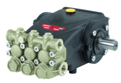
Pressure systems in industrial applications typically operate within defined performance windows: the Interpump E3B2515 series, for instance, delivers consistent performance at 250 bar (3,625 psi) with a flow rate of 15 L/min at 1,450 rpm. When actual field measurements deviate from these baseline specifications, the deviation pattern itself becomes diagnostic data. A 10% pressure loss coupled with normal flow rates suggests seal degradation or internal leakage. Conversely, pressure within specification but reduced flow indicates impeller cavitation or inlet restriction.
The critical diagnostic principle is this: pressure and flow rate must be evaluated simultaneously, never in isolation. A pump maintaining pressure while delivering insufficient flow has failed in a fundamentally different way than one that cannot generate pressure at all. This distinction determines whether repair strategy involves fluid power system components, mechanical restoration, or complete replacement.
Temperature also participates in the diagnostic framework. Elevated fluid temperatures (typically indicating 60°C+) combined with pressure loss suggest mechanical friction increases from bearing wear or seal degradation. Cold start pressure spikes followed by rapid pressure drop indicate viscosity-dependent inlet restriction or thermal expansion seal issues. System designers and maintenance engineers must establish baseline thermal profiles during commissioning to establish meaningful deviation thresholds.
Pressure Measurement and Diagnostic Testing Procedures
Accurate pressure measurement forms the foundation of all industrial pump diagnostics. The CBM Glycerin Stainless Steel Pressure Gauge (0/+4 bar, G1/4 connection) provides mechanical pressure indication suitable for system circuit monitoring, while electronic multimeters enable electrical circuit verification of pressure transducers and control systems. For high-frequency pressure monitoring or transient analysis, digital test equipment becomes essential.
The diagnostic test sequence should follow this structured approach: First, establish baseline pressure under known operating conditions—idle state, zero load, and rated operational load. For the Interpump PUMP E3B2515I R operating at rated 1,450 rpm, baseline pressure should stabilize at 250 bar within 30 seconds of start-up. Record this reference value as the standard against which all subsequent measurements are compared.
Second, measure pressure at three distinct circuit points: pump discharge (primary measurement point), any intermediate pressure relief valve location, and system return/tank pressure. Pressure differential analysis between these points reveals where energy losses occur. If discharge pressure measures 240 bar but relief valve inlet measures 235 bar, 5 bar has dissipated across connecting lines and valves—a normal loss. If the same measurement shows 220 bar at relief valve inlet, circuit leakage or component failure requires investigation.
Third, perform flow rate measurement using calibrated flow meters or observing volumetric displacement over timed intervals. The Interpump E3B2515I R specified at 15 L/min should deliver within ±5% of this rate under rated conditions. Flow below this range with normal pressure indicates mechanical degradation; flow reduction coupled with pressure loss typically confirms cavitation or inlet blockage.
For electrical system components, use the CBM Automatic Multimeter MM420 to verify voltage presence at solenoid coils, pressure transducer signal output (typically 4-20 mA ranges), and control circuit continuity. Measure AC voltage at pump motor terminals; deviation greater than ±10% from nameplate voltage indicates electrical system problems rather than pump mechanical failure.
Component-Specific Diagnostics and System Integration
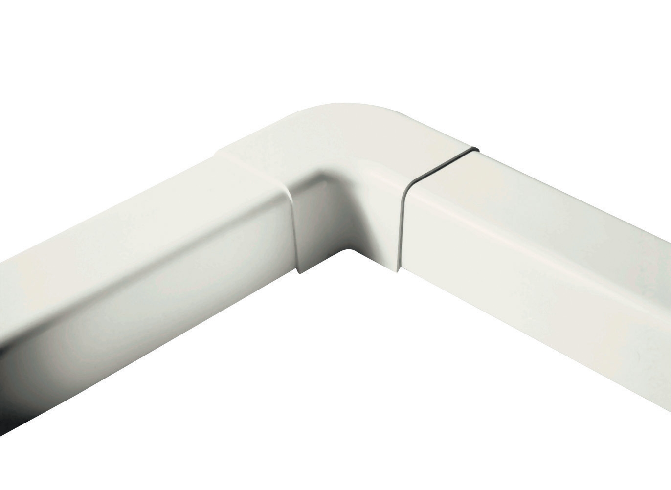
Industrial pump systems rarely consist of isolated pump units—they integrate pressure relief valves, check valves, directional control elements, and piping networks that must function as cohesive systems. The CBM Flat Elbow 90° (60mm) and similar piping components are not merely passive conduits; they represent potential failure points where pressure drop accumulation, dead-leg cavitation, or corrosion-induced leakage can degrade overall system performance.
When troubleshooting composite system failures, pressure measurement must extend through all major piping elements. A pump-to-manifold pressure differential exceeding 3 bar typically indicates either excessive line length, undersized tubing (causing velocity-induced losses), or partial blockage from particulate contamination or crystalline deposits in fluid lines. Flushing procedures or line replacement become warranted when such differentials are confirmed across multiple test cycles.
Relief valve function is critical to proper system diagnostics. A pump unable to reach rated pressure may actually be functioning normally with a relief valve stuck in open position, or conversely, a relief valve failing to open may be masking pump flow capability reduction. Test relief valve function by gradually increasing system load (restricting return flow) and confirming pressure rise follows expected curves. Relief valve cracking pressure should match equipment documentation; variance exceeding ±5% indicates internal spool wear or contamination.
For systems incorporating Interpump PUMP E3B1515 DX with RS500H Gearbox arrangements, power transmission efficiency between motor, gearbox, and pump becomes diagnostic. Measure current draw at motor terminals; excessive current (>20% above rated) with normal pressure and flow output indicates bearing friction increases from wear. Monitor gearbox housing temperature; readings above 80°C suggest bearing degradation or lubrication film breakdown.
Real-World Application Examples and Failure Pattern Recognition
A municipal water treatment facility operating Interpump E3B2515 series pumps reported gradual pressure loss over eight weeks, declining from 250 bar to 215 bar while flow rates remained constant at 14.8 L/min. Initial assessment suggested pump seal failure; however, systematic testing revealed pressure loss was confined to the pump discharge line to manifold connection. Inspection discovered calcium carbonate deposits accumulated internally within pipe elbows—a phenomenon occurring in hard water environments without proper inhibitor treatment. Line flushing and chemical treatment restoration resolved the issue without pump replacement, saving significant capital expenditure.
A processing facility experiencing intermittent pump cavitation (audible noise, vibration spikes) conducted inlet circuit analysis and discovered the suction strainer had accumulated biological fouling typical of warm climates. Establishing automated strainer monitoring and quarterly flushing schedules eliminated the cavitation issue. The lesson: pressure system failures often originate in peripheral circuits rather than pump core mechanisms.
Temperature-driven failures in high-ambient environments require specific attention. Facilities in tropical regions (Global Southeast Asia applications, for instance) frequently experience pump thermal runaway where system temperature exceeds fluid viscosity design limits (typically 60°C maximum sustained operation). Installing secondary coolers or expanding reservoir volume to increase thermal mass prevents pressure spikes and viscosity-related cavitation that otherwise damage pump internals irreversibly.
Diagnostic Equipment Selection and Best Practices
Establishing a comprehensive diagnostic toolkit is essential for procurement engineers responsible for pump system acquisition and maintenance planning. Minimum requirements include pressure measurement devices (mechanical gauges for visual circuit monitoring and electronic transducers for data logging), electrical test equipment for circuit verification, and flow measurement capability for validation of operational parameters.
The CBM Non-Contact Voltage Detector provides rapid safety verification before electrical circuit investigation, identifying energized components without direct contact—critical for personnel safety during troubleshooting procedures. Complement this with multimeter capability for quantitative voltage and current measurements across control circuits and solenoid elements.
Establish baseline documentation practices: record pressure, flow, temperature, and electrical parameters during commissioning of new systems. Archive these baseline measurements with equipment nameplate data and operational manuals. Deviation trending over months and years reveals performance degradation patterns before catastrophic failures occur, enabling predictive maintenance scheduling and procurement planning for replacement components. Digital data logging equipment enables remote monitoring, particularly valuable for distributed facility operations across multiple geographic locations.
Closing and Next Steps
Industrial pump pressure system troubleshooting requires disciplined methodology combining pressure measurement protocols, flow rate validation, electrical circuit verification, and systematic component analysis. Rather than assuming pump failure when performance degrades, engineers should execute structured diagnostic sequences that isolate root causes and guide appropriate remediation strategies—whether component repair, circuit modification, or equipment replacement.
3G Electric supplies the diagnostic instrumentation, replacement components, and system integration expertise required to execute these troubleshooting procedures effectively across global industrial applications. Our team of industrial equipment specialists can assist with diagnostic protocol development, equipment selection, and maintenance planning to minimize unplanned downtime and optimize capital investment in your pressure system infrastructure. Contact 3G Electric today to discuss your specific pump system challenges and receive tailored diagnostic guidance from our technical team.