Industrial Pump and Piping Integration: A Practical Application Guide for Global Maintenance Teams
Industrial pump systems require more than just selecting the right pump—proper integration with compatible piping, connectors, and supporting infrastructure is critical to system longevity and performance. For maintenance teams and service engineers managing industrial equipment across global facilities, understanding the relationship between pump specifications, flow dynamics, and piping geometry directly impacts operational efficiency, safety, and downtime costs. This guide explores the practical considerations for integrating centrifugal and gear-driven pumps into existing industrial systems, focusing on real-world application scenarios and the technical criteria that drive component selection.
Understanding Pump-to-Piping Integration Fundamentals
The foundation of a reliable industrial pump system lies in the seamless integration of the pump unit with the broader fluid conveyance network. When a pump is selected for an application—whether handling coolant circulation, hydraulic fluid transfer, or pressurized liquid supply—the downstream piping must be engineered to accommodate the pump's output specifications without introducing excessive backpressure, turbulence, or mechanical stress.
Pump integration begins with understanding three critical parameters: volumetric flow rate (measured in liters per minute or gallons per minute), system pressure rating (in bar or PSI), and the physical connection interface. Industrial pumps operate within defined performance envelopes. For example, a compact gear pump designed for industrial applications might deliver 15 liters per minute at 250 bar pressure, while consuming approximately 7.13 kilowatts of electrical power. These specifications are not arbitrary—they represent the boundary conditions within which the pump operates safely and efficiently.
The piping network must respect these boundaries. If piping is undersized relative to the pump's flow output, pressure drop accelerates, reducing effective flow at the application point and forcing the pump to work harder. Conversely, oversized piping increases material costs, system weight, and installation complexity without performance benefit. The optimal approach involves selecting pipe diameters and connector types that maintain velocity within industry-standard ranges (typically 2-4 meters per second for return lines, 1-2 meters per second for pressure lines) while minimizing pressure loss.
Connection geometry also plays a critical role. Abrupt changes in direction, sharp bends, and mismatched connector sizes introduce turbulence and localized pressure spikes that can damage seals, accelerate component wear, and reduce system efficiency. This is where the choice of elbow angles, connector materials, and routing architecture becomes essential.
Selecting Pump Models and Compatible Piping Components
When evaluating industrial pump options for specific applications, maintenance teams must cross-reference pump performance data with available piping and connector inventory. Consider a scenario where a facility requires a compact, high-pressure pump for a pressurized fluid transfer circuit. The Interpump E3B2515I pump delivers 15 liters per minute at up to 250 bar (3,625 PSI), with a rated power output of 7.13 kilowatts. This pump is compact (measuring 265mm in length with a weight of 9.5 kilograms) and suitable for direct coupling to electric motors or gearbox configurations.
The pump's 250-bar pressure rating establishes the minimum pressure class required for all downstream components. Standard industrial piping for 250-bar applications typically uses DN16 to DN20 (16-20mm nominal diameter) steel tubing or equivalent high-pressure hose, depending on material compatibility and flexibility requirements. The 15 L/min flow rate guides pipe sizing: at this flow rate, DN16 tubing maintains acceptable velocity without excessive pressure drop.
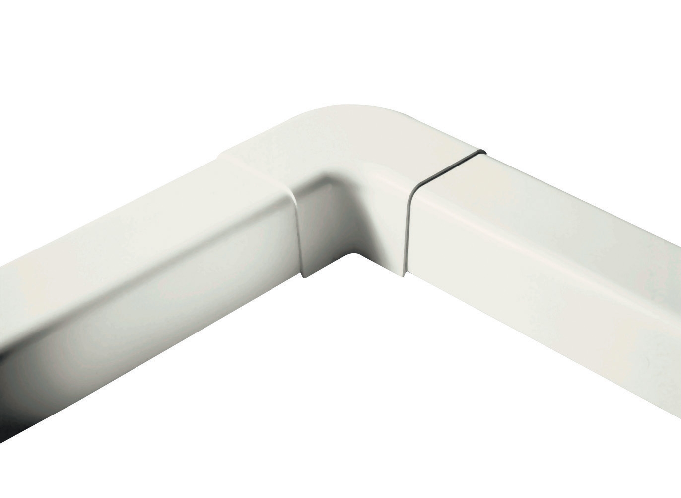
Connection architecture is equally important. Rather than rigid 90-degree elbows that create sharp pressure discontinuities, many facilities specify flat or swept-radius elbow connectors that reduce turbulence and localized stress. The CBM flat elbow 90° connector at 60mm is an example of a component designed to accommodate larger-diameter piping while minimizing pressure loss through gradual direction change. For systems where space is constrained, flat elbows offer superior performance compared to standard compression fittings.
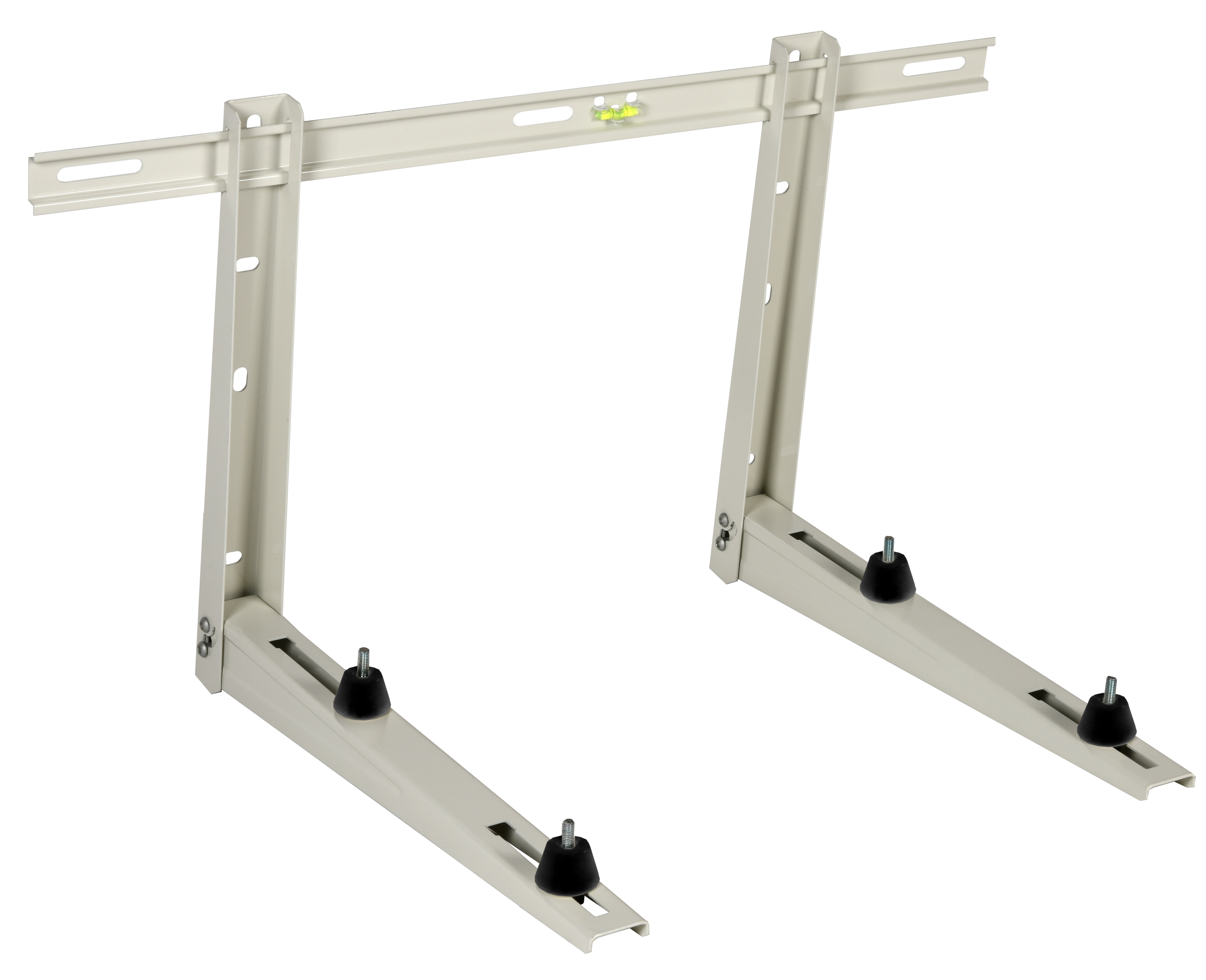
Pump mounting and support also influence piping integration. Improperly supported pumps transmit vibration into the piping network, causing fatigue failures in hose connections and accelerating seal degradation. Industrial mounting brackets designed to support equipment weight while isolating vibration ensure stable pump operation and reduce stress on connected piping. For pumps rated at 250 bar and handling continuous flow duty, rigid mounting on appropriately rated support structures is non-negotiable.
Alternative pump configurations, such as the Interpump E3B2515 L model or the E3B1515 DX with integral valve and gearbox combination, offer flexibility for applications requiring specific shaft orientations, valve integration, or speed reduction. Each configuration maintains the same core performance envelope (15 L/min, 250 bar) but accommodates different installation geometries and control requirements.
Real-World Application Scenarios: Industrial Burners and Supporting Systems
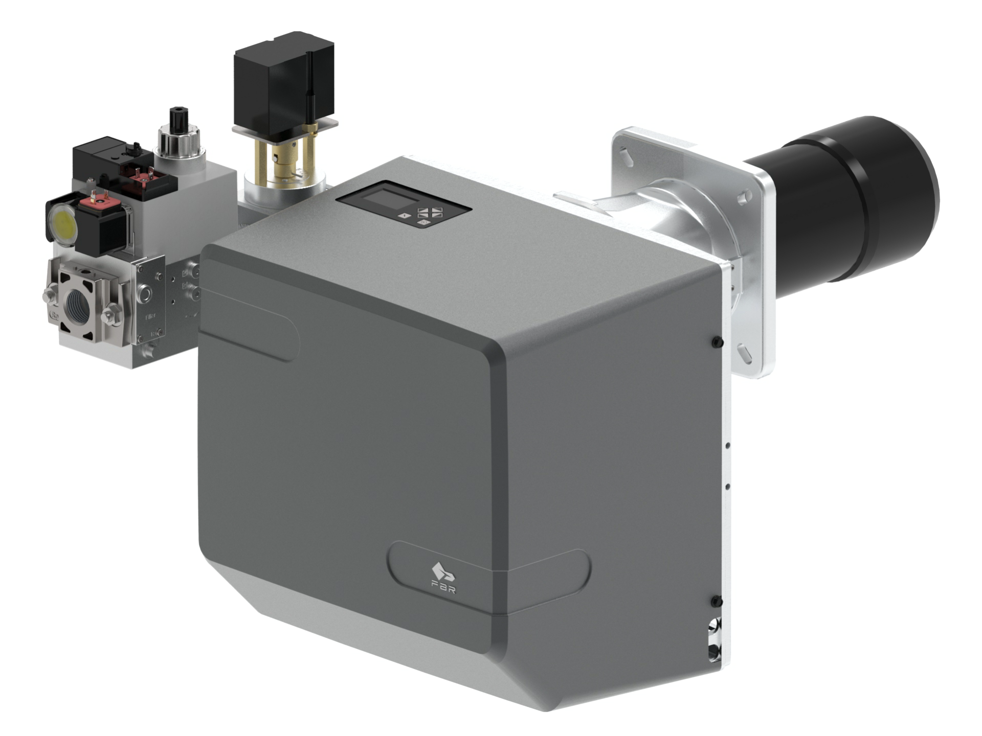
In industrial heating and combustion applications, pump and piping integration takes on additional complexity due to the interaction between fuel supply systems, burner control circuits, and safety instrumentation. Modern industrial burners—such as the FBR Gas X5/MF burner designed for fully modulating PID control—require precise, stable fuel delivery regulated by supporting pump and pressure-control systems.
The FBR burner operates across a wide power range (minimum 69.8 kW to maximum 349 kW) and requires fuel gas delivery at 27-33 mbar minimum supply pressure for natural gas applications. To achieve stable combustion across this modulation range, the fuel supply circuit typically incorporates a small gear pump (similar to the Interpump models discussed above) connected to the gas train with precisely sized piping and pressure regulators. The pump delivers steady, low-pressure gas flow to the burner's proportional valve, which modulates actual fuel rate in response to load demand.
In this application, piping must be sized for low-pressure gas flow (typically 50-100 mm/s velocity) to minimize pressure drop and delay time between valve actuation and flame response. Oversized piping creates sluggish response characteristics that compromise combustion stability, while undersized piping introduces excessive pressure loss that degrades burner turndown performance. Piping connections must also resist vibration from the burner's high-pressure combustion chamber, making rigid mounting and vibration isolation essential design considerations.
Best Practices for Pump-to-Piping System Integration
Pressure Rating Alignment: Ensure all piping components, hose assemblies, and fittings are rated for at least the pump's maximum operating pressure. Use a safety factor of at least 1.5x for pressure-containing components.
Flow Velocity Verification: Calculate piping diameter based on desired flow velocity for the specific fluid type. For oil circuits, target 2-4 m/s on pressure lines; for return lines, 2 m/s is acceptable. Use this formula: Velocity = (Flow in L/min / 60) / (Pipe area in cm²) / 100.
Connection Geometry: Minimize sharp bends and abrupt direction changes. Use swept-radius elbows or flat connector geometry where space permits. Install strainers upstream of gear pumps to protect internal components from debris.
Vibration and Support: Mount pumps on vibration-isolating brackets or resilient feet. Secure piping runs with appropriate clamps to prevent resonant vibration and fatigue failure.
Maintenance Access: Plan piping routing to allow filter changes, pump removal, and pressure gauge installation without extensive system disassembly. This consideration pays dividends during ongoing maintenance cycles.
Temperature and Material Compatibility: Select piping materials compatible with the fluid being pumped. Steel piping works well for mineral oils; corrosion-resistant stainless steel is preferred for aqueous fluids or high-temperature applications.
Monitoring and Troubleshooting Pump System Integration
Once a pump system is integrated and operational, ongoing performance monitoring is essential. Pressure gauges installed at key circuit points reveal integration problems early. For example, an unexpectedly high pressure drop across the pump outlet indicates either undersized piping or internal pump wear. By installing a CBM glycerin-filled stainless steel pressure gauge at the pump discharge and a second gauge downstream at the application load, maintenance teams can quickly isolate whether pressure loss occurs in the piping network or within the pump itself.
Abnormal vibration or noise in the piping system suggests inadequate support, loose connections, or cavitation within the pump. Service engineers should visually inspect piping mounts and tighten any loose clamps or fittings. If vibration persists after mechanical inspection, the issue may be system flow starvation (undersized inlet piping) or excessive pressure relief cycling—both conditions that compromise pump longevity.
For industrial facilities managing multiple pump systems across different process applications, systematic documentation of each circuit's pressure profile, flow rate, and vibration baseline enables predictive maintenance planning and failure prevention.
Conclusion and Guidance for Your Facility
Successful industrial pump integration transcends component selection alone. It requires understanding the hydraulic and mechanical relationships between pump output specifications, piping geometry, and system operating conditions. Whether you are upgrading existing fuel supply circuits for industrial burner systems, replacing worn pumps in cooling or circulation loops, or designing new process systems from the ground up, the principles outlined in this guide apply across global industrial settings.
3G Electric has been serving industrial facilities worldwide since 1990, providing distribution of industrial pumps, piping components, pressure instrumentation, and burner systems suited to diverse application requirements. Our technical team can help your maintenance staff evaluate specific pump models, select compatible piping and connector components, and design integration approaches that optimize reliability and efficiency for your unique facility conditions.
Contact 3G Electric today to discuss your pump system requirements or request technical support for existing equipment integration challenges. Our service engineers are ready to help you achieve peak performance from your industrial equipment infrastructure.