Industrial Pump vs. Gas Burner System Integration: A Technical Comparison for Global Applications
Maintenance teams and service engineers managing industrial systems often encounter scenarios where industrial pumps and gas burners operate as integrated components within larger heating, cooling, and fluid transfer systems. While these devices serve fundamentally different functions, understanding their technical specifications, operational parameters, and integration requirements is critical for optimizing system performance, reducing downtime, and ensuring safety across manufacturing, HVAC, and industrial maintenance sectors globally. This technical comparison explores the performance characteristics, selection criteria, and real-world deployment considerations for both equipment categories.
Understanding System Integration: Pumps and Burners in Industrial Context
Industrial systems rarely operate in isolation. In typical manufacturing environments—from heat treatment facilities to large-scale HVAC installations—gas burners provide the thermal energy required to heat fluids, while industrial pumps circulate those heated (or cooled) fluids throughout the system. The coordination between these two components directly impacts overall system efficiency, response time, and operational reliability.
Gas burner systems function as the primary heat source, converting fuel energy into thermal output measured in kilowatts (kW). Modern industrial burners employ modulating combustion control to match thermal demand dynamically, improving fuel efficiency and reducing cycling stress on connected piping and pump systems. Industrial pumps, conversely, are rated by flow capacity (liters per minute or gallons per minute) and maximum pressure (bar or PSI), determining how effectively they move heated or cooled fluids from the burner or heat exchanger to end-use points.
The critical integration challenge lies in pressure matching and flow synchronization. If pump discharge pressure exceeds system design limits, relief valves must engage, wasting energy. If flow rates are insufficient for the thermal load, burner output cannot be effectively distributed, creating hot spots and reducing system responsiveness. Engineers must therefore evaluate both components against identical system parameters: required thermal load, circuit volume, acceptable pressure drop, and response time requirements.
Technical Specifications: Comparative Analysis of Key Parameters
Let us examine the specifications of industry-standard equipment from two leading manufacturers to illustrate the technical comparison framework:
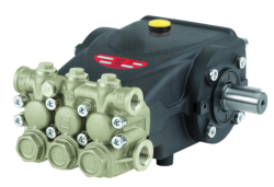
Industrial Pump Performance: The Interpump E3B2515I pump represents a common mid-range specification in global industrial applications. Operating at 1,450 RPM with a displacement-based flow rate of 15 liters per minute (3.96 US gallons per minute), this unit delivers a maximum pressure of 250 bar (3,625 PSI / 25 MPa). The motor consumes 7.13 kW (9.7 horsepower) at rated conditions, with a compact footprint of 265 mm in overall length. Weighing just 9.5 kg, this pump suits installations where space constraints require vertical or horizontal mounting with minimal structural reinforcement.
The Interpump E3B2515S variant offers identical flow, pressure, and power specifications but with alternative shaft configurations to accommodate different coupling arrangements. Both models feature gear-driven displacement, making them suitable for applications requiring steady, non-pulsating flow characteristics essential in precision heating circuits and critical cooling loops.
Gas Burner Thermal Output: The FBR GAS X5/MF burner presents a more complex specification profile. With a maximum thermal output of 349 kW and minimum output of 69.8 kW, this modulating burner accommodates variable load conditions typical in industrial environments. The 370-watt fan motor provides high-pressure combustion air, ensuring efficient fuel atomization across the entire modulation range. Operating at IP40 electrical protection, it suits environments with moderate moisture and dust exposure. The fuel pressure requirement of 27/33 mbar (Natural Gas/LPG) establishes baseline piping design parameters and regulator specifications.
System Pairing Logic: A 7.13 kW pump circulating at 15 L/min through a 349 kW maximum burner represents a system where the thermal source substantially exceeds the pump's hydraulic power. This is typical and intentional—the burner heats large volumes of fluid (potentially 300+ liters in a heating vessel), while the pump provides controlled circulation. The pump's 250 bar pressure rating ensures it can overcome circuit friction losses even in extended pipe runs common in industrial facilities.
Real-World Application Examples: Integration Scenarios
Scenario 1: Industrial Process Heating (Food/Chemical Manufacturing)
A mid-sized food processing facility requires closed-loop heating of 500 liters of thermal oil to 180°C for pasteurization. The FBR GAS X5/MF burner provides 280 kW of modulating heat (operating at approximately 80% of rated maximum), while the Interpump E3B2515I pump circulates the thermal oil at 15 L/min. This configuration ensures approximately 33 complete circuit turnovers per hour (500L ÷ 15 L/min = 33 minutes per cycle), providing uniform heating without thermal stratification. The pump's 250 bar rating provides margin for heat exchanger fouling and future circuit expansion.
Scenario 2: HVAC System with Variable Load Response
A large commercial HVAC system serving a manufacturing campus experiences fluctuating heating demand (60–340 kW) across four thermal zones. The modulating FBR X5 burner adjusts thermal output via PID control, while two Interpump E3B2515S pumps in parallel circulation provide 30 L/min combined flow. This redundant configuration allows one pump maintenance without system shutdown, critical in facilities where thermal stability directly impacts product quality.
Scenario 3: System Upgrade and Retrofit
An aging industrial heating system originally sized for 150 kW output requires capacity expansion to 280 kW without complete piping replacement. Using the modulating FBR GAS X5/MF allows thermal output adjustment via software, while the existing Interpump pump remains adequate if flow testing confirms circuit friction losses remain below 50 bar at design flow. This retrofit approach reduces capital expenditure while extending equipment service life.
Technical Comparison: Pump vs. Burner Specifications
| Parameter | Interpump E3B2515I/S Pump | FBR GAS X5/MF Burner | Application Implication |
|---|---|---|---|
| Primary Output Rating | 15 L/min (3.96 GPM) | 69.8–349 kW (modulating) | Pump flow is fixed; burner output adjusts to load |
| Maximum Pressure | 250 bar (3,625 PSI) | Fuel: 27–33 mbar | System relief valve must be set below pump max; burner pressure is minimal |
| Power Consumption | 7.13 kW continuous | 0.37 kW fan + burner control | Pump is primary electrical load; fan motor is auxiliary |
| Operating Speed | 1,450 RPM fixed | Modulating via PID control | Pump speed is constant; burner ramps up/down based on temperature feedback |
| Weight | 9.5 kg | Not specified (approx. 50–70 kg with combustion head) | Pump allows flexible mounting; burner requires stable foundation and air intake |
| Control Interface | On/Off or VFD-compatible | PID modulation + safety interlocks | Burner requires dedicated control logic; pump integrates into main system PLC |
| Maintenance Interval | 2,000–4,000 hours (seal inspection) | Annual combustion head cleaning; nozzle service at 1,000 hours | Pump requires hydraulic fluid analysis; burner needs fuel system inspection |
Selection Criteria and System Design Considerations
When integrating pumps and burners, maintenance engineers should evaluate the following criteria:
1. Thermal-to-Hydraulic Load Matching: Calculate system volume and desired heat-up time. A 500-liter system heating from 20°C to 80°C (60 K temperature rise) requires approximately 35 MJ of thermal energy. At 280 kW burner output, heating time is roughly 2 minutes of continuous operation. Pump circulation rate must then distribute this heat evenly—15 L/min provides one complete circuit turnover every 33 minutes, adequate for most applications.
2. Pressure Drop Analysis: Conduct detailed friction loss calculations across heat exchangers, piping, and control valves. If total circuit friction exceeds 150 bar at design flow, pump pressure rating (250 bar) leaves only 100 bar margin for future modifications—insufficient for retrofits. In such cases, larger-displacement pump models or parallel pumping becomes necessary.
3. Burner Modulation Range: The FBR GAS X5/MF provides a 5:1 turndown ratio (349 kW maximum ÷ 69.8 kW minimum). This suits applications with variable loads. Systems with constant demand should consider fixed-output burners, which eliminate hunting and reduce control complexity.
4. Redundancy and Availability: For critical processes, parallel pump arrangements and dual burner configurations reduce single-point failure risk. Maintenance teams should specify quick-disconnect couplings and isolation block valves to enable component service without full system shutdown.
Measurement and Monitoring Integration
Effective system oversight requires monitoring pressure and temperature at critical points. For pump-burner systems, maintenance teams should install:
- Discharge pressure gauge at pump outlet (confirm operating pressure stays 20–30 bar below relief setpoint)
- Temperature probe at heat exchanger inlet and outlet (validate thermal output and circuit flow)
- Fuel pressure gauge at burner inlet (typically 27–33 mbar for Natural Gas)
- Return-line pressure/temperature sensors to detect heat exchanger fouling
Integrating these sensors with a building automation system or industrial PLC enables predictive maintenance—rising discharge pressure may indicate pipe scaling or heat exchanger blockage, while decreasing outlet temperature suggests declining burner efficiency.
Conclusion and Next Steps
Industrial pump and gas burner systems represent complementary technologies that, when properly integrated, deliver reliable thermal distribution across manufacturing and HVAC applications worldwide. Success depends on rigorous specification matching, accurate system modeling, and ongoing performance monitoring. The Interpump E3B2515I pump and FBR GAS X5/MF burner represent proven solutions for mid-range industrial applications, but correct pairing requires detailed engineering analysis tailored to your specific system demands.
Whether you're upgrading an existing system, troubleshooting performance issues, or planning a new industrial heating or cooling installation, the expert team at 3G Electric is prepared to guide you through component selection, system integration, and long-term maintenance strategy. Contact our technical support team today to discuss your specific application requirements and ensure your pump and burner systems operate at peak efficiency.