Understanding High-Pressure Nozzle Maintenance & Service in HVAC Systems
High-pressure nozzles are critical components in modern HVAC systems, particularly in fuel atomization and pressure wash applications. As an HVAC contractor, understanding proper maintenance and service procedures ensures optimal system performance, reduces downtime, and extends equipment lifespan. With over 35 years of experience distributing industrial equipment globally, 3G Electric recognizes that nozzle-related failures account for approximately 40% of HVAC system inefficiencies.
The integrity of your nozzle assembly directly affects combustion efficiency, spray patterns, and overall system reliability. Whether you're servicing atomizing nozzles, flat jet nozzles, or quick-coupling systems, implementing consistent maintenance protocols prevents costly repairs and maintains warranty compliance. This guide provides practical, field-tested procedures for HVAC contractors operating in diverse global markets.
Pre-Service Inspection and Diagnostic Procedures
Visual Assessment and Performance Evaluation
Begin every maintenance cycle with a comprehensive visual inspection. Before disconnecting any components, observe the system during normal operation to identify anomalies:
- Spray pattern degradation: Uneven or asymmetrical spray indicates internal restriction or nozzle misalignment
- Pressure fluctuations: Monitor gauge readings for unexplained drops, which suggest blockages or seal deterioration
- Audible changes: Unusual grinding, whistling, or chattering sounds often precede component failure
- Combustion characteristics: Changes in flame color, smoke production, or ignition delay warrant immediate nozzle inspection
Pressure Testing and Flow Rate Verification
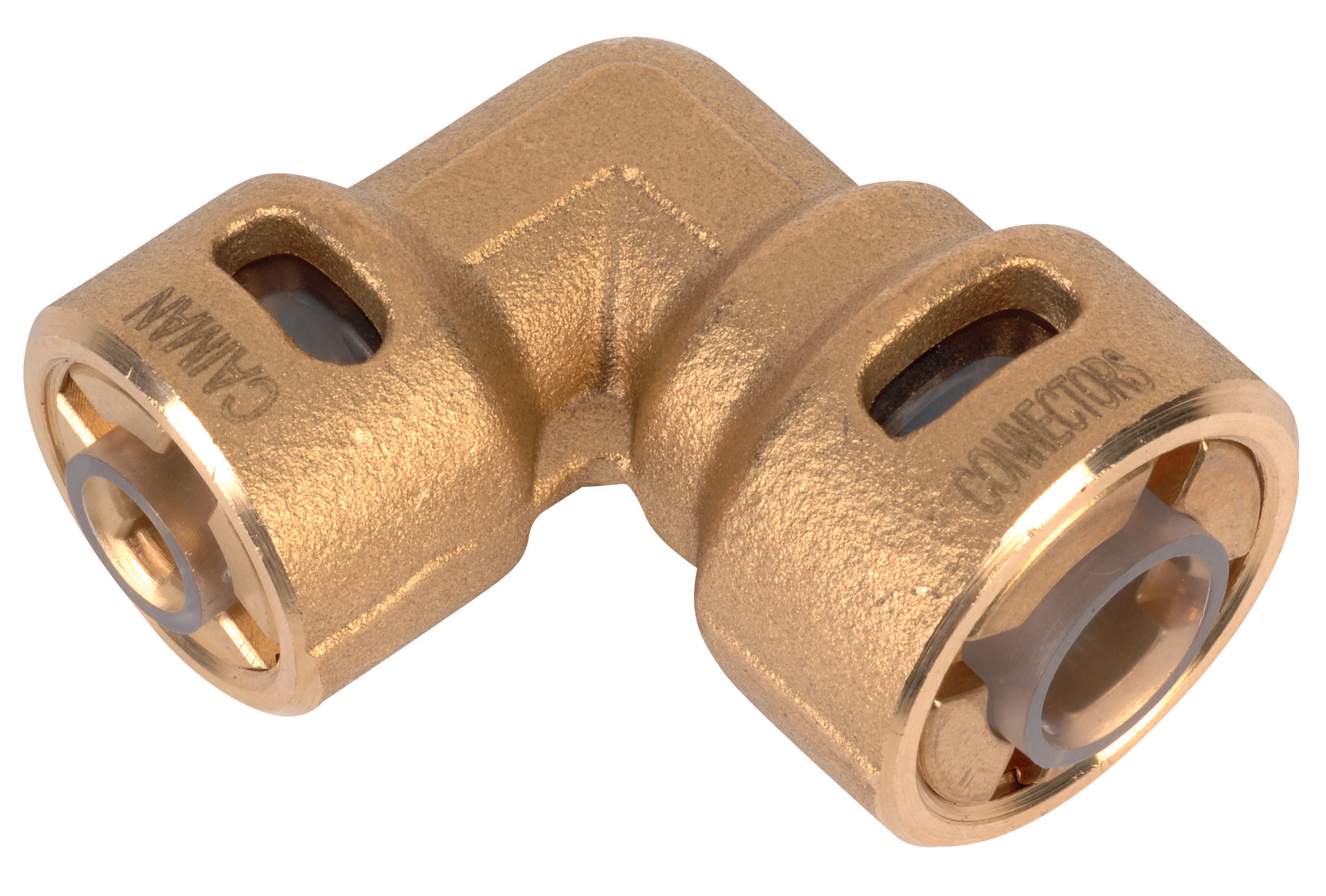
Establish baseline measurements before removing components. Document existing pressure readings across the system, paying particular attention to pressure drops at quick-coupling connections. The CBM Quick Coupling 90° Pressure Reduction 1/4*3/8 experiences normal pressure reduction according to specifications; excessive drops beyond rated values indicate seal wear.
Measure actual flow rates at the nozzle outlet using calibrated containers and timers. Compare results against manufacturer specifications—deviation exceeding 5% suggests internal deposits or wear. Record all measurements in your maintenance log for trend analysis; consistent degradation indicates accelerating component failure requiring intervention.
Thermal Imaging and Surface Temperature Analysis
Utilize thermal imaging cameras to detect hot spots around nozzle housings and quick-coupling assemblies. Localized temperature variations indicate friction from stuck pistons, internal blockages creating turbulent flow, or seal degradation allowing pressurized fluid escape. Elevated temperatures at connection points suggest improper seating or thread contamination.
Cleaning, Cleaning Procedures, and Blockage Removal
Safe Disconnection and System De-pressurization
Before any service work, follow these critical safety steps:
- Shut down the system and allow 30 minutes for pressure decay
- Open all isolation valves and bleed pressure manually using bleed screws
- Install pressure gauges on downstream outlets to verify zero pressure
- Place absorbent materials around connection points to contain residual fluid
- Tag the system with lockout/tagout devices if required by local regulations
Nozzle Extraction and Initial Assessment
Carefully remove nozzles using appropriately-sized wrenches—over-tightening during removal damages internal components. Immediately inspect the removed nozzle:
- Examine the orifice opening under magnification for crystallized deposits, carbon buildup, or partial blockage
- Inspect external surfaces for corrosion, erosion patterns, or impact damage
- Check the seat face for discoloration indicating thermal stress or chemical reaction
- Evaluate the connection thread condition; cross-threading during installation causes irreversible damage
For flat jet nozzles like the CBM Flat Jet Nozzle HP 1/4"M BSPT Index 25 Angle 15° or CBM Flat Jet Nozzle HP 1/4"M BSPT Index 055 Angle 15°, position the nozzle under adequate lighting and use needle lights for orifice inspection.
Chemical Cleaning and Solvent Selection
Select cleaning agents based on deposit composition:
- Carbon and soot deposits: Use approved industrial cleaning solvents with soak times of 4-8 hours
- Mineral deposits from water contamination: Employ mild acidic solutions (white vinegar or citric acid) for 2-4 hours
- Fuel varnish and oxidized residues: Utilize ultrasonic cleaning tanks with compatibility-rated solvents for 15-20 minute cycles
- Resinous deposits from degraded hydraulic fluids: Extended soak periods (24+ hours) in penetrating solvents may be necessary
Never use wire brushes or abrasive materials on orifice surfaces—these tools remove material and enlarge openings, permanently altering spray characteristics. Instead, use soft brass brushes for external cleaning and wooden or plastic picks for internal orifice work.
After chemical cleaning, rinse components thoroughly with approved flushing fluid, then dry completely using compressed air. Allow 2 hours minimum drying time before reinstallation to prevent residual solvent contamination.
Component Replacement Strategies and System Integration
Determining Replacement vs. Repair Decisions
Repair makes economic sense only for easily-accessible deposits and minor wear. Replace nozzles when:
- Orifice diameter enlargement exceeds 0.05mm from original specification
- Seat face shows pitting, erosion, or heat discoloration that cleaning cannot remove
- Thread damage compromises secure seating
- Spray angle deviation exceeds ±2° from specification
- Internal seal integrity is compromised (evident from fluid weeping)
Knowing when to replace prevents repeated callbacks and maintains system reliability. Document replacement decisions in your service records to establish component lifespan baselines for your accounts.
Installing Replacement Nozzles and Couplings
When upgrading to replacement nozzles, ensure spray characteristics match original specifications. The CBM Flat Jet Nozzle HP 1/4"M BSPT Index 50 Angle 40° offers different flow rates and angles than other flat jet models—verify the correct selection before installation.
Installation procedure:
1. Clean all connection ports with lint-free cloths; remove any protective caps or plugs only immediately before installation
2. Install new connection sealants (PTFE tape or thread sealant compound) following manufacturer specifications
3. Thread the nozzle hand-tight first, then tighten with wrenches using firm, controlled pressure—never over-torque
4. For quick-coupling connections, like the CBM Quick Coupling 90° Pressure Reduction 1/4*3/8, align the coupling axis perpendicular to mounting surfaces before engagement
5. Bleed air from nozzle lines by opening downstream bleed screws during initial pressurization
When replacing pressure reduction couplings, verify that nominal pressure ratings match system requirements. Undersized couplings cavitate and fail prematurely; oversized couplings reduce system responsiveness.
Mounting Hardware and Structural Considerations
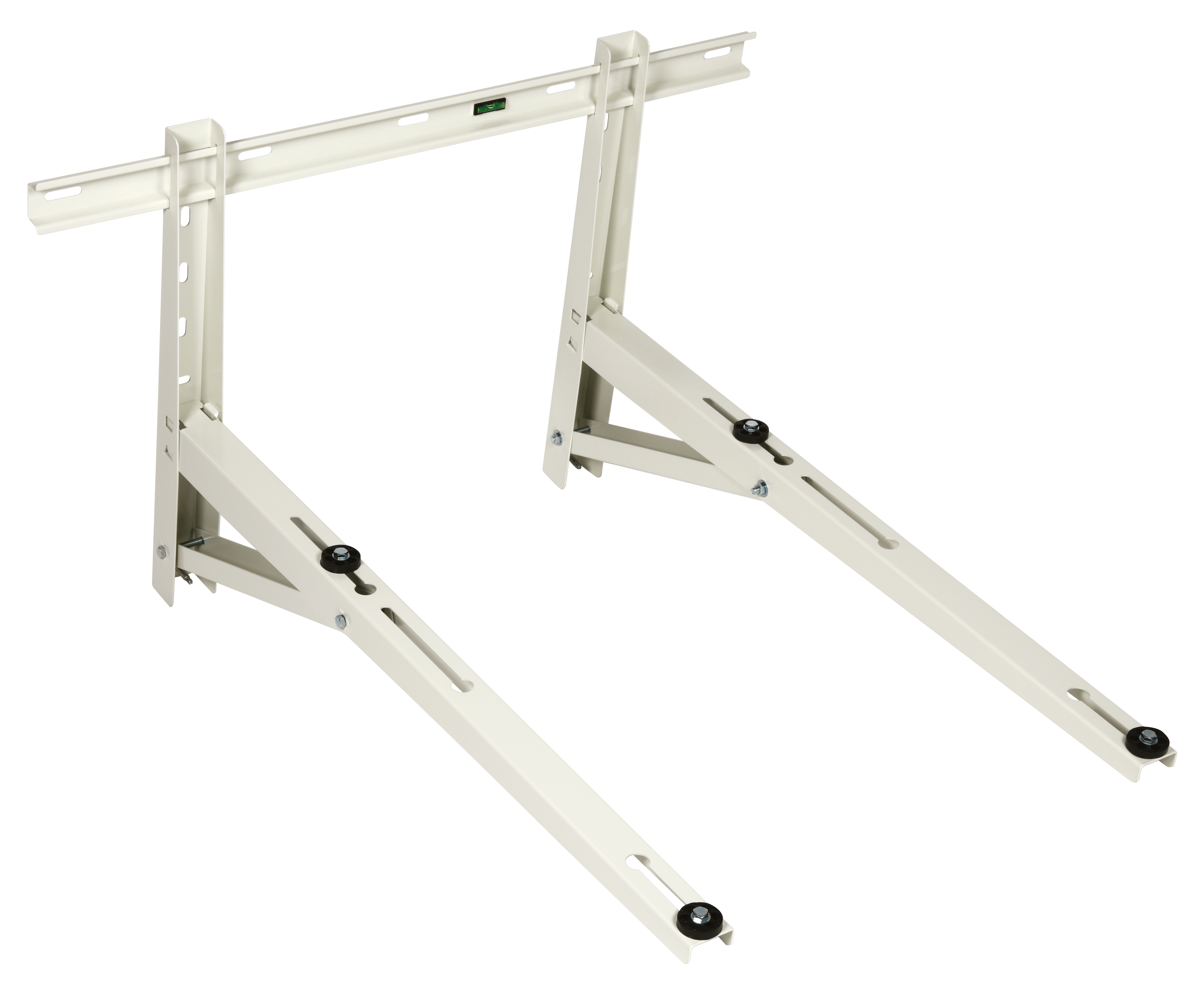
Proper mounting prevents vibration-induced fatigue and provides stable spray delivery. The CBM Wall Bracket 1000 secures nozzle assemblies and quick-coupling manifolds against wall surfaces or equipment frames. When installing mounting brackets:
- Position brackets to minimize cantilever distances from nozzle outlets
- Use vibration-damping materials between metal components
- Ensure bracket height places nozzles at manufacturer-specified working distances
- Verify anchor fasteners match substrate materials—concrete requires expansion anchors; steel requires welded or bolted connections
Improper mounting creates resonance frequencies matching system operating pressures, generating vibration that loosens connections and promotes seal failure.
Maintenance Scheduling and Performance Monitoring
Establishing Preventive Maintenance Intervals
Develop maintenance schedules based on operating conditions:
- Low-contamination environments (closed-loop systems, pre-filtered supply): Inspect every 2,000 operating hours
- Moderate-contamination conditions (industrial facilities with periodic fluid changes): Inspect every 1,000 hours
- High-contamination environments (outdoor applications, environments with airborne particulates): Inspect every 500 hours
Adjust intervals downward when handling fluids with poor filterability or when operating at maximum rated pressures. Document all service intervals in your preventive maintenance management system and communicate recommended service timing to your HVAC customers.
Fluid Analysis and Condition Monitoring
Implement fluid sampling programs for systems using hydraulic fluids or fuel oil. Analyze samples for:
- Particulate count: ISO cleanliness codes indicating filtration effectiveness
- Water content: Measures moisture contamination; levels above 0.5% cause nozzle degradation
- Viscosity changes: Deviation from specification indicates thermal stress or chemical breakdown
- Acid number: Rising values signal oxidation and corrosive degradation
Fluid condition directly affects nozzle longevity. Poor fluid quality accelerates component wear regardless of proper maintenance procedures.
Documentation and Trend Analysis
Maintain detailed service records including:
- Inspection dates and findings
- Component part numbers and serial numbers
- Measurements (pressure, flow rate, spray angles)
- Cleaning methods and solvents used
- Replacement components installed
- Thermal imaging data and photographs
- System runtime hours since last service
Analyze trends across service intervals to predict failures. If cleaning intervals progressively shorten, investigate upstream filtration and fluid condition. If pressure readings decline consistently, seal deterioration is likely. Early trend detection enables proactive maintenance rather than reactive emergency repairs.
Conclusion
Mastering high-pressure nozzle maintenance and service positions HVAC contractors as trusted technical partners for industrial clients worldwide. Drawing on 35+ years of experience, 3G Electric understands that systematic inspection, proper cleaning techniques, and timely component replacement directly correlate with customer satisfaction and system reliability. By implementing these field-proven procedures, you reduce unplanned downtime, extend equipment lifespan, and establish recurring maintenance revenue streams.
Invest in quality replacement components like CBM nozzles and quick-coupling systems, maintain comprehensive service documentation, and continuously refine your maintenance protocols based on performance data. This commitment to technical excellence distinguishes your contracting business in competitive global markets.