Understanding Controls & Safety in Singapore HVAC Applications
Controls & Safety systems are the nervous system of modern HVAC installations. For contractors operating in Singapore's demanding industrial and commercial environment, understanding how to properly install, commission, and maintain these systems is essential for system reliability, regulatory compliance, and client satisfaction.
With over 35 years of experience as a leading industrial equipment distributor, 3G Electric has supported thousands of HVAC contractors across Southeast Asia. We've observed that successful implementations require more than just component selection—they demand practical knowledge of installation procedures, commissioning protocols, and daily operational best practices specific to Singapore's climate and regulatory environment.
This guide focuses on the practical, hands-on aspects of Controls & Safety systems that HVAC contractors encounter daily. You'll discover installation techniques that minimize commissioning time, operational procedures that prevent costly downtime, and troubleshooting approaches that solve problems efficiently.
Pre-Installation Planning and System Assessment
Defining Your System Requirements
Before purchasing any Controls & Safety components, conduct a thorough system assessment. This foundational step prevents specification errors and ensures you select components that match your actual operational needs.
Start by documenting your burner specifications: fuel type (gas, oil, or dual-fuel), nominal heat output, and ignition method. Singapore's tropical climate requires special attention to ambient temperature ranges and humidity levels, which affect component selection and protective measures.
Next, map your control hierarchy. Determine what functions your system must perform: burner start/stop control, flame monitoring, pressure management, air damper modulation, and safety interlocks. For complex systems, create a functional block diagram showing how individual components communicate and what safety functions each component provides.
Document your pilot configuration—is direct ignition required, or will intermittent/continuous pilot ignition work for your application? The Kromschroder Relay BCU 570WC1F1U0K1-E supports multiple ignition modes, making it suitable when flexibility is needed. However, understanding your specific requirements first ensures you don't over-specify components or, conversely, discover mid-installation that your choice won't work.
Consider Singapore's electrical supply characteristics. Most installations operate at 230V single-phase or 400V three-phase. Verify that all components you select match your facility's available supply, and account for voltage fluctuations that can occur during peak demand periods.
Environmental and Safety Considerations
Singapore's high humidity, salt-laden air in coastal areas, and compact industrial spaces create specific challenges for Controls & Safety installations.
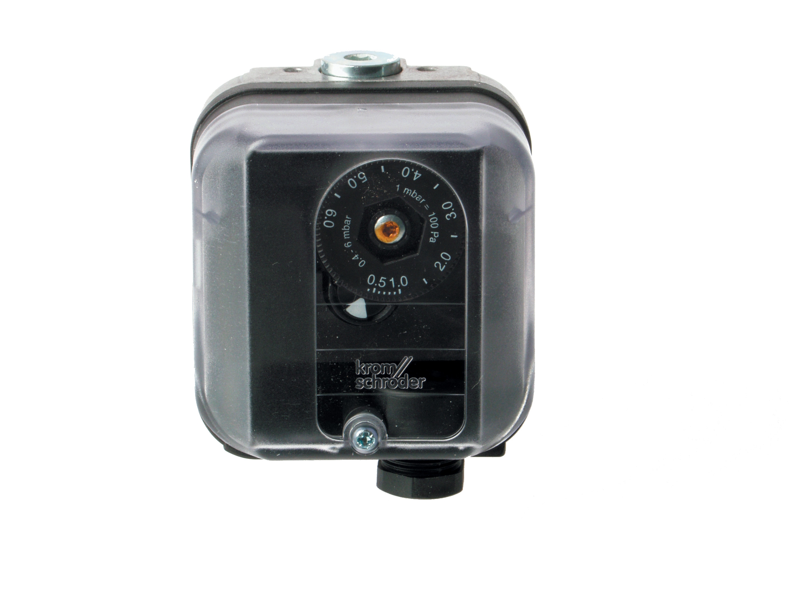
Plan your component mounting locations to minimize exposure to condensation and corrosive environments. Pressure switches like the Kromschroder DG 50U/6 perform reliably when properly protected from environmental stressors. Install them in clean, dry enclosures with adequate ventilation to prevent moisture accumulation.
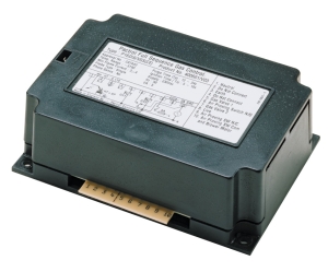
Address thermal management early. Flame control modules such as the Pactrol Housing P 16 DI CE generate heat during operation. Ensure your control panel design includes adequate ventilation or cooling to maintain component operating temperatures within specifications. In Singapore's climate, overheating is a common cause of premature component failure.
Identify all safety interlocks required by your application and facility regulations. Beyond basic flame monitoring, consider interlocks for air supply failure, fuel pressure anomalies, and system lockout conditions. These elements must be specified and tested before installation begins.
Installation Techniques and Wiring Best Practices
Component Positioning and Cable Management
Proper physical installation sets the foundation for reliable operation. Position your safety relay and control components logically within your control panel, grouping related functions together for easier troubleshooting and maintenance.
Place the safety relay (such as the Siemens LFL 1.622) in a central location where it can easily receive signals from all connected sensors and distribute control outputs. Ensure adequate spacing around the relay for heat dissipation and future service access—a minimum of 50mm clearance on all sides is recommended.
When mounting pressure switches, ensure the connection point is accessible and the switch orientation matches manufacturer specifications. The DG 50U/6 pressure switch requires stable mounting to prevent vibration-induced signal noise. Use vibration-damping brackets, especially in installations with high-frequency burner cycling.
Cable routing deserves careful attention. Separate power cables and low-voltage signal cables by at least 150mm to prevent electromagnetic interference. Use shielded cables for all signal lines from flame sensors and pressure switches. In Singapore's humid environment, proper shielding prevents false signals caused by moisture-induced leakage currents.
Label every wire with both ends clearly marked using standardized notation matching your control diagram. This simple practice saves enormous amounts of troubleshooting time during commissioning and future maintenance. Use engraved labels or permanent markers—adhesive labels can fail in humid conditions.
Gas Block and Regulator Installation
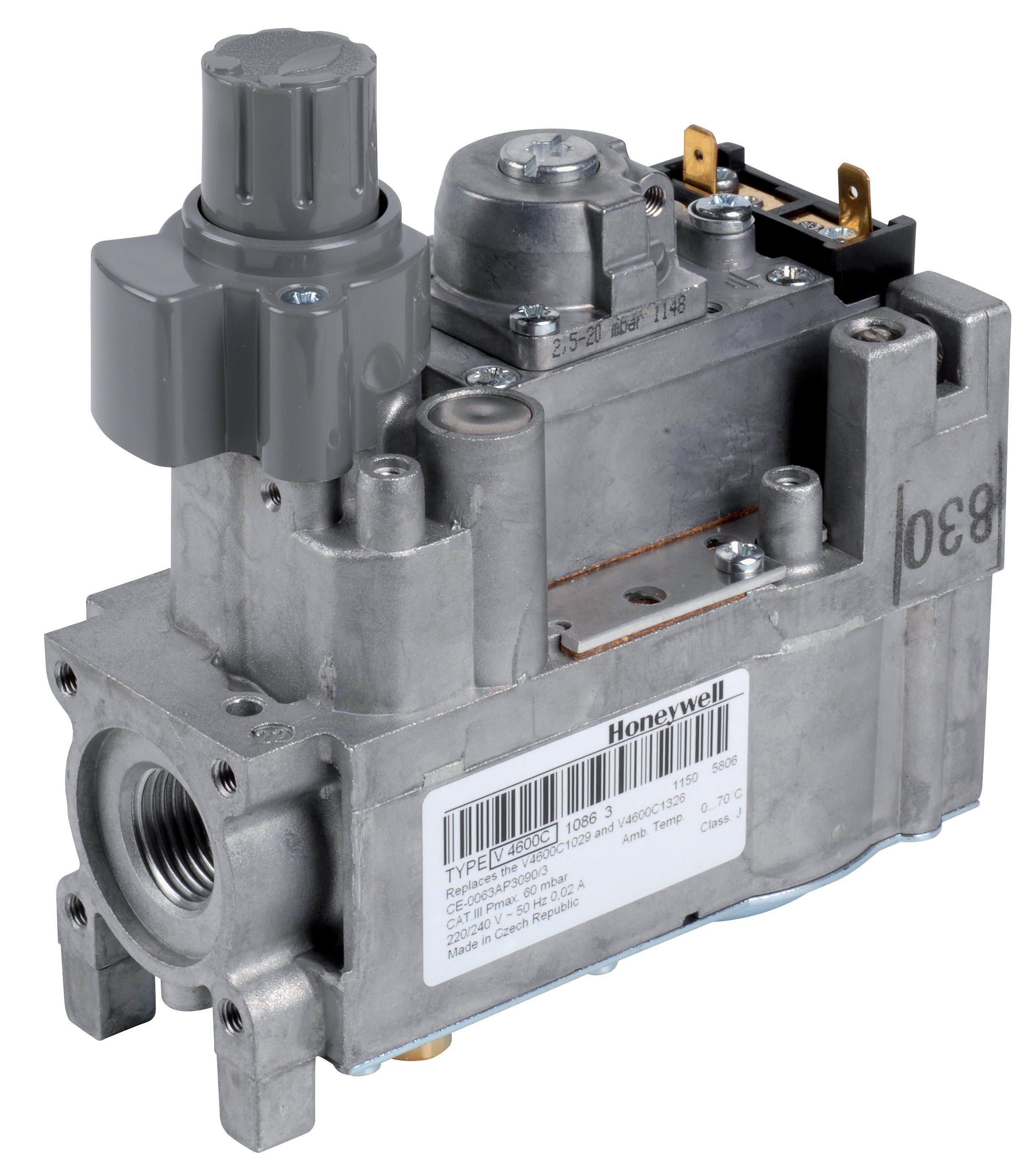
The Honeywell Gas block VK 4105 C 1041 U requires precise installation to function as designed. This electric modulating pressure regulator controls gas flow based on control signals, so installation quality directly affects burner performance and safety.
Install the gas block downstream of any manual isolation valves and upstream of the burner fuel inlet. Verify that pilot and main pressure tapping points connect to the correct input/output ports as specified in your control diagram. The M8 x 1 pilot connection and M5 pressure feedback threading must be correctly configured—reversed connections will prevent the system from functioning.
When installing tubing connections to the gas block, use appropriate fittings for your operating pressure range. In Singapore, many contractors use copper tube fittings, but verify compatibility with your specific fuel gas and operating pressures. Leak-test all connections before commissioning using soap solution—no pressurized gas leaks are acceptable in urban Singapore installations.
Configure the pressure regulator's feedback signal carefully. The pressure feedback connection tells the regulator what fuel pressure it's actually delivering, allowing it to adjust modulation. If this signal is weak or erratic, the burner will struggle to maintain stable operation.
Commissioning and System Validation Procedures
Pre-Ignition Checklist
Before attempting first ignition, perform a comprehensive pre-ignition checklist. This step prevents damage to components and catches installation errors while they're still easy to fix.
Verify all electrical connections match your control diagram exactly. Check that the safety relay receives power and exhibits normal startup behavior (indicator lights should cycle). Confirm that all fuel shutoff solenoids are de-energized (valves closed) in the idle state.
Test all sensor circuits individually with your multimeter. Pressure switches should show open circuits when unpressurized and closed circuits when hand-pressurized above their set point. Flame sensor circuits should show high impedance with no flame present. These simple tests verify that your wiring is correct before fuel flows.
Inspect the burner itself for any debris or damage. Confirm that air supply dampers move freely and reach their mechanical limits. Check that all safety interlocks (if mechanical) operate properly through their full range.
Phased Ignition Testing
Conduct ignition testing in discrete phases, validating each function before moving to the next.
Phase 1: Control Power and Safety Relay Initialization
Apply power to the control circuit and observe the safety relay. The Kromschroder BCU 570WC1F1U0K1-E should initialize without errors. If the relay indicates fault conditions, do not proceed—investigate and resolve the fault.
Phase 2: Air Purge Cycle
Initiate the startup sequence and verify that the system executes a proper air purge cycle. The burner fan should run for the specified purge duration (typically 10-30 seconds) before fuel is introduced. This critical safety function prevents explosive fuel-air mixtures from forming.
Phase 3: Pilot Ignition (if applicable)
If your system uses pilot ignition, observe the ignition transformer output and verify that the pilot lights reliably. The Pactrol Housing P 16 DI CE generates the ignition energy needed for successful pilot lighting. Monitor the flame sensor's response—it should detect the pilot flame within 2-3 seconds of ignition attempt.
Phase 4: Main Burner Light-Off
Once the pilot is proven, initiate main burner fuel flow. Main burner light-off should occur smoothly without hesitation or flame instability. If the main burner struggles to light or exhibits unstable flame, check fuel pressure and air/fuel mixing before proceeding.
Phase 5: System Stability Verification
Run the system at nominal load for at least 15 minutes, monitoring flame stability, fuel pressure, and all safety signals. Record all readings. The system should maintain stable operation without nuisance shutdowns or oscillating control signals.
Pressure Switch and Safety Function Testing
Once normal operation is confirmed, systematically test every safety function. The Kromschroder DG 50U/6 pressure switch is typically rated SIL 3, meaning it must be tested to verify that it actually stops the burner when fuel pressure drops below its set point.
With the system running at normal load, gradually reduce fuel pressure (by closing a needle valve on the fuel line if one is available for testing) while monitoring the control system's response. The pressure switch should trigger a burner shutdown when pressure drops to its set point. The safety relay should command fuel shutoff, and the system should safely transition to shutdown.
Repeat this test multiple times to verify consistent performance. Document the exact pressure at which shutdown occurs—this becomes your baseline for future maintenance reference.
Test flame loss response by interrupting the flame signal while the burner is running. The system should recognize flame loss within the allowed response time (typically 2-5 seconds) and safely shut down. For systems using the Siemens LFL 1.622 safety relay with UV flame detection, confirm that the UV sensor is properly positioned and unobstructed.
Operational Best Practices and Ongoing Maintenance
Daily Operational Procedures
Establish simple daily checks that your operators can perform. Even in highly automated systems, occasional manual verification prevents small problems from becoming large ones.
Have operators visually inspect the flame during normal operation. A steady, stable flame of consistent color and size indicates proper air/fuel mixing and burner health. Any color change (becoming more yellow or orange), excessive flickering, or uneven flame pattern suggests an issue worth investigating before the next maintenance interval.
Instructed operators should note any unusual sounds during burner operation. The ignition transformer may emit a high-frequency hum—this is normal. However, grinding sounds, whistling, or loud pops indicate problems with fuel atomization, air supply, or ignition timing that require attention.
Monitor fuel consumption patterns. If the system suddenly requires higher fuel input to maintain the same heat output, burner efficiency is declining. This typically indicates carbon buildup on the burner nozzles or air introduction passages, requiring professional cleaning.
Preventive Maintenance Intervals
Establish a preventive maintenance schedule based on your burner's usage intensity and Singapore's environmental conditions.
Monthly Inspection (1-2 hours)
Physically inspect all visible components for corrosion, loose connections, or signs of damage. In coastal Singapore areas, salt-laden air accelerates corrosion—monthly inspection catches problems early. Verify that all cable connections remain tight and no wires show signs of abrasion or heat damage.
Quarterly Function Testing (2-3 hours)
Perform the same safety function tests you conducted during commissioning: pressure switch response, flame loss detection, system startup sequence. Document all results. If any function is slower to respond or less consistent than baseline readings, investigate before the next operational cycle.
Annual Professional Service (4-6 hours)
Engage a qualified service technician to perform comprehensive testing of the safety relay and control components. This includes calibration verification of pressure switches and flame sensor sensitivity checks. Professional service should include cleaning of ignition electrodes, inspection of the pilot nozzle (if equipped), and replacement of any components showing age-related performance degradation.
Troubleshooting Common Operational Issues
HVAC contractors often encounter recurring issues. Understanding the root causes and solutions saves time and client frustration.
Nuisance Shutdowns During Normal Operation
When the burner shuts down unexpectedly without obvious fault conditions, the most likely causes are intermittent signal losses or threshold sensitivity problems. Check signal cable connections first—corrosion or moisture in connectors often causes intermittent shutdowns. If connections are clean, gradually reduce the pressure switch set point by 10-15 kPa and retest. Sometimes pressure oscillations near the switch set point cause repeated triggering. If the issue persists, the pressure switch may require replacement or recalibration.
Slow or Difficult Light-Off
If the burner requires multiple ignition attempts or lights inconsistently, fuel pressure or ignition energy is typically insufficient. Verify fuel supply pressure at the burner inlet matches specification (usually 15-25 kPa for typical gas burners). Check ignition transformer output voltage—it should match the design specification (typically 8-12 kV for direct ignition systems). Inspect the ignition electrode gap and condition; carbon buildup or erosion reduces ignition reliability. Clean electrodes with appropriate tools and verify gap spacing before retesting.
Unstable Flame or Fluctuating Heat Output
Flame instability usually indicates air/fuel ratio problems. In Singapore's humid environment, moisture in fuel lines occasionally causes issues. First, verify that the air damper moves smoothly through its full range and reaches proper position for your load. If air damper movement is sluggish, the modulating regulator (such as the Honeywell VK 4105) may not be receiving proper control signals. Check all wiring to the regulator. If the regulator responds too slowly to load changes, the control loop response time settings in the safety relay may need adjustment—consult your control system documentation.
Conclusion
Successful Controls & Safety implementation in Singapore's HVAC environment combines thorough pre-installation planning, careful physical installation, methodical commissioning, and disciplined ongoing maintenance. By following the practical procedures outlined in this guide, HVAC contractors can deliver systems that operate reliably, safely, and efficiently.
3G Electric's 35+ years of experience supporting industrial equipment users across Southeast Asia has shown that contractors who invest time in proper installation and commissioning enjoy significantly lower failure rates and higher client satisfaction. The components discussed here—the Kromschroder relays and pressure switches, Siemens safety controls, Honeywell gas blocks, and Pactrol ignition modules—are industry-standard solutions trusted by professionals throughout Singapore.
Your success depends on understanding not just what components to use, but how to install them correctly, test them thoroughly, and maintain them systematically. Master these practical skills, and you'll build a reputation for delivering Controls & Safety systems that work consistently and safely throughout their service life.