Understanding High-Pressure Nozzle & Coupling Systems in Industrial Operations
High-pressure nozzles and quick couplings form the critical interface between pressurized fluid systems and application equipment in industrial environments. As an authorized global distributor with 35+ years of operational experience, 3G Electric recognizes that Maintenance & Service failures in these components represent one of the most common causes of system downtime across manufacturing, cleaning, and combustion applications.
Unlike storage tanks or pump systems, nozzles and couplings experience extreme wear conditions: continuous pressure cycling, thermal stress, particle contamination, and mechanical impact. Procurement engineers must understand that these are consumable items requiring systematic replacement protocols rather than indefinite repair strategies. The nozzle's precision spray geometry—governed by internal orifice design and angle—degrades gradually, while coupling seals deteriorate from repetitive connection cycles and chemical exposure.
Diagnostic Procedures for Nozzle Performance Degradation
Spray Pattern Assessment and Flow Rate Monitoring
The most reliable indicator of nozzle deterioration is spray pattern deviation, detectable before complete system failure. Begin diagnostics by establishing baseline performance metrics:
- Spray Geometry Analysis: High-pressure nozzles like the CBM Flat Jet Nozzle HP 1/4"M BSPT Index 25 Angle 15° produce precisely defined flat jet patterns with specific angle characteristics. Progressive orifice erosion manifests as cone-shaped spray expansion rather than tight flat jet geometry. Use visual inspection under operating pressure—comparing spray patterns against manufacturer documentation or archived photographs from system commissioning.
- Flow Rate Measurement: Collect discharge volume over timed intervals (typically 30-60 second samples) at consistent system pressure. Document baseline flow rates during initial setup. A 10-15% reduction typically indicates early orifice degradation; reductions exceeding 25% require immediate component replacement to prevent efficiency loss and uneven application patterns.
- Pressure Drop Calculation: Deploy differential pressure gauges at nozzle inlet and downstream application points. Abnormal pressure drops suggest internal orifice blockages from particulate contamination rather than wear-related degradation. This distinction is critical: blockages require system flushing, while erosion demands component replacement.
Identifying Coupling Seal Failures
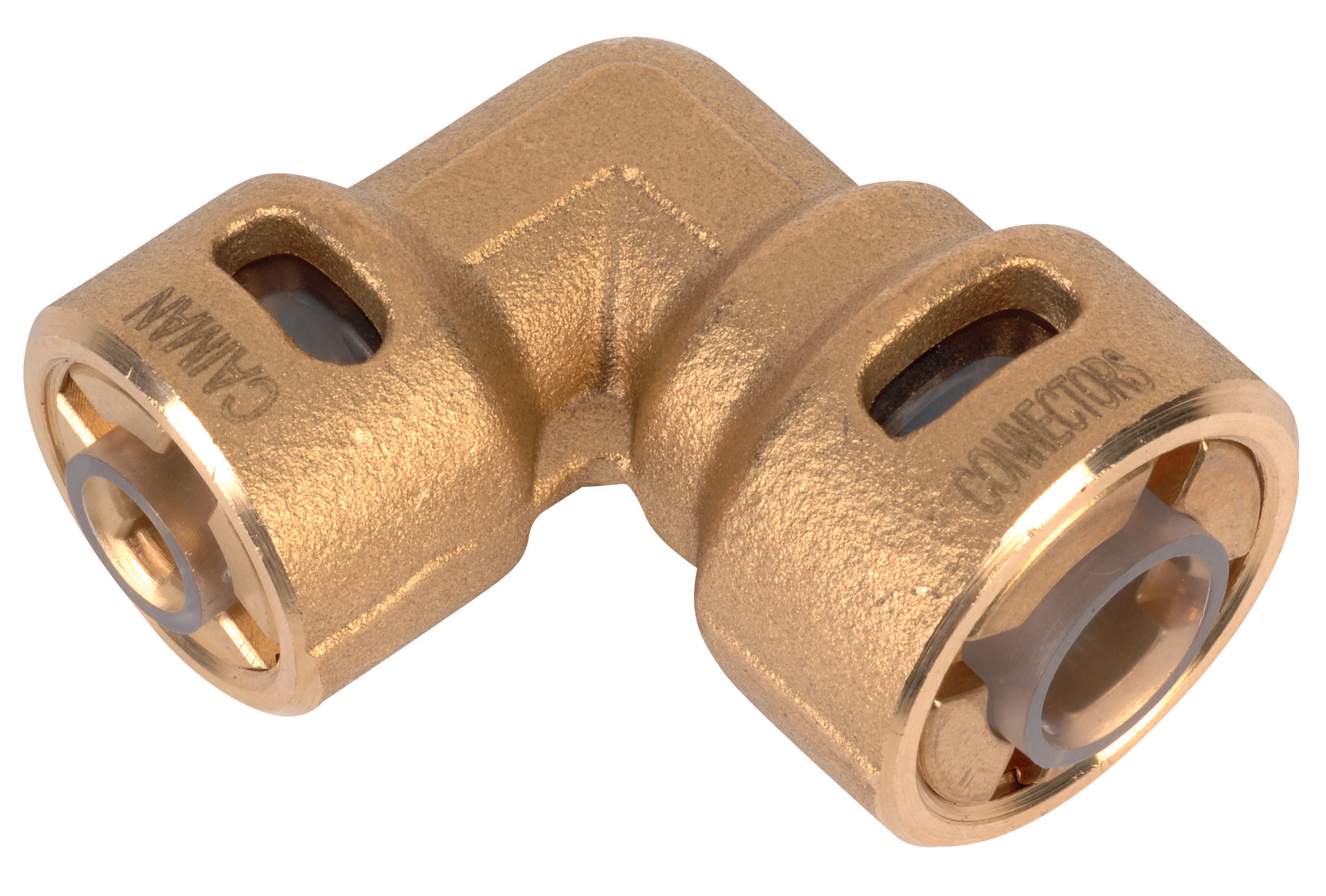
Quick couplings like the CBM Quick Coupling 90° Pressure Reduction 1/4*3/8 incorporate precision seals rated for specific pressure ratings and fluid types. Coupling failures present distinct diagnostic signatures:
- Leak Location Mapping: External leakage at the coupling body interface indicates seal degradation, while leakage at the disconnect point suggests O-ring compression loss or mechanical damage. Distinguish between active pressure leaks (occurring during pressurized operation) and weep seepage (slow dripping during idle periods). Weep seepage often precedes complete seal failure by 10-20 operating hours.
- Connection Resistance Testing: Worn couplings require increasing manual force to connect and disconnect. Excessive resistance indicates seal swelling (from incompatible fluid chemistry) or damage to sealing surfaces from particle entrainment. This resistance increase represents a critical maintenance trigger, as forced connections can fracture coupling bodies or create internal pressure channels.
- Pressure Rating Verification: Couplings degrade differently across pressure ranges. The 90° pressure reduction coupling functions optimally within specific pressure bands. Exceeding rated pressure accelerates seal degradation and can cause catastrophic coupling failure. Compare actual system operating pressure against coupling nameplate ratings—undersizing couplings for pressure reduction applications often becomes cost-apparent only after premature failures.
Component Selection Strategy for Maintenance & Service Operations
Nozzle Specification Alignment with Application Requirements
Nozzle selection extends beyond spray angle specifications. Procurement engineers must cross-reference three critical parameters:
Spray Index and Angle Compatibility: The CBM Flat Jet Nozzle HP 1/4"M BSPT Index 055 Angle 15° and CBM Flat Jet Nozzle HP 1/4"M BSPT Index 50 Angle 40° represent different application scenarios despite similar size designations. Index 055 nozzles deliver narrow, concentrated spray patterns ideal for precision cleaning or combustion applications requiring tight spray focus. Index 50 configurations with 40° angles produce broader coverage patterns suitable for wash-down or area treatment operations. Selecting the wrong index for existing application geometry causes uneven coverage, requiring mid-cycle nozzle replacements that disrupt production schedules.
Material Composition and Fluid Compatibility: CBM nozzles are manufactured from hardened stainless steel or specialized ceramics depending on spray index. Verify material compatibility with system fluids—certain solvents, oils, or corrosive cleaning compounds accelerate nozzle degradation. Document material specifications during procurement to establish replacement intervals aligned with actual operational conditions rather than theoretical worst-case scenarios.
Operating Pressure Classification: High-pressure nozzles rate at specific maximum operating pressures (typically 250-400 bar for industrial applications). Operating at 85-95% of rated pressure extends component life, while sustained operation above 95% shortens service intervals by 30-50%. When specifying replacement nozzles, consider whether system upgrades (pressure relief adjustments, pump capacity limitations) could reduce pressure stress and extend component lifespan.
Coupling Selection for System Architecture
Quick coupling selection involves pressure class, connection volume, and leakage tolerance assessment:
Pressure Class Matching: The pressure reduction coupling incorporates internal orificing to reduce downstream pressure, making it suitable for systems with sensitive components downstream that cannot tolerate full inlet pressure. Verify that coupling pressure reduction aligns with downstream component ratings—oversized pressure reduction creates unnecessary flow restriction and heat generation.
Connection Cycle Frequency: Couplings subjected to frequent connect-disconnect cycles (>20 cycles daily) experience accelerated seal wear. Specify premium seal grades and schedule replacements at 50% of theoretical service life when frequent cycling is inherent to operations. Conversely, semi-permanent installations can utilize standard seal grades with extended replacement intervals.
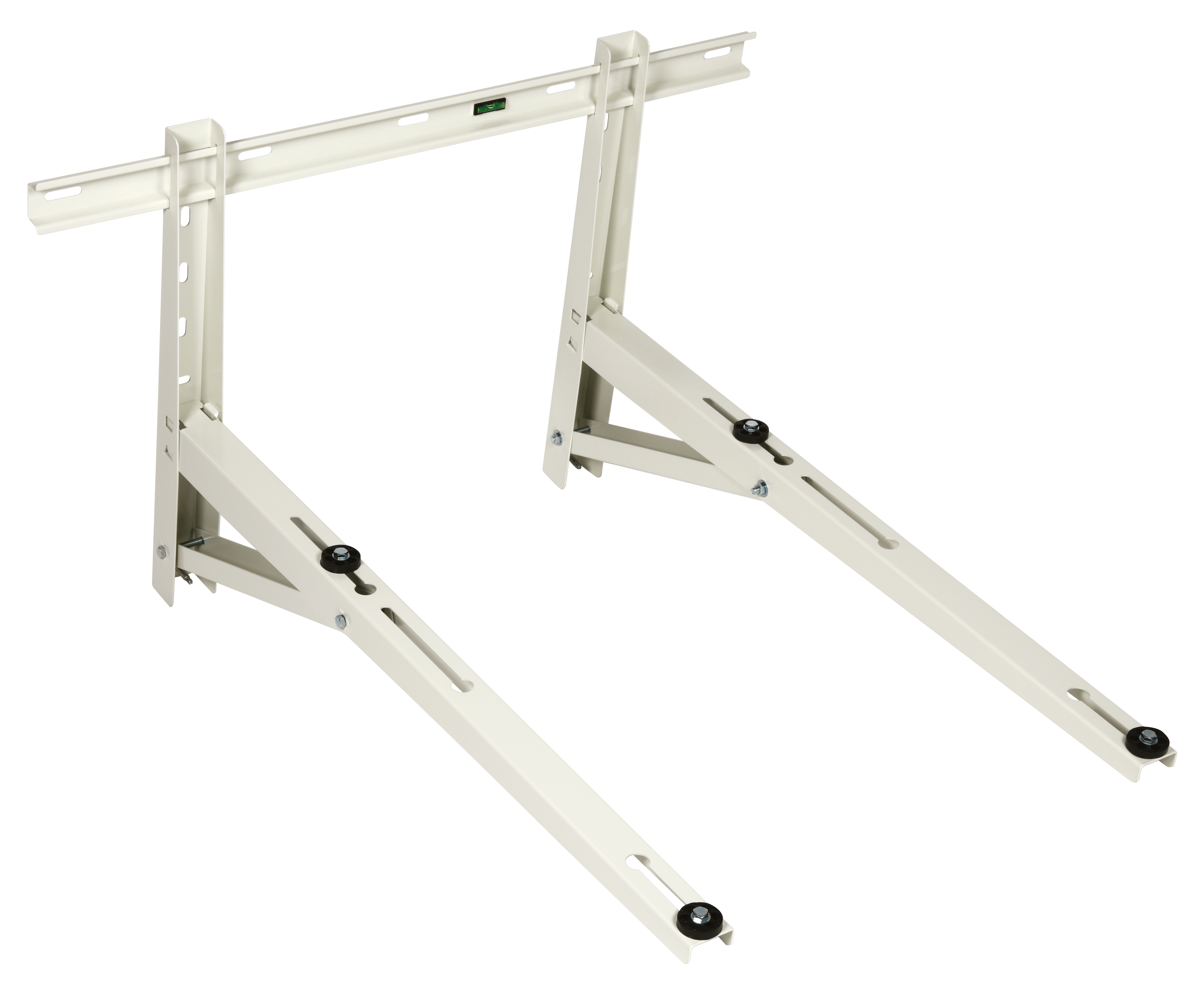
System Architecture Integration: The CBM Wall Bracket 1000 provides structural support for nozzle assemblies and coupling manifolds, reducing vibration-induced micro-movements that accelerate seal wear. Including proper mounting infrastructure during system design or retrofit prevents mechanical stress that compounds normal wear patterns.
Preventive Maintenance Protocols and Replacement Scheduling
Condition-Based Replacement Triggers
Develop documented replacement procedures based on three monitoring parameters:
Operating Hour Thresholds: Establish baseline replacement intervals through initial field testing. Track actual component life across different applications and operating pressures. For high-pressure nozzles, typical intervals range 500-2000 operating hours; couplings extend 1000-5000 hours depending on seal quality and connection frequency.
Visual Inspection Checkpoints: Implement weekly visual inspections during system operation. Document spray pattern consistency, external coupling leakage presence, and pressure gauge stability. Photograph spray patterns monthly to detect gradual pattern degradation invisible to memory-based comparisons.
Performance Metric Monitoring: Maintain historical data on flow rates, pressure differential, and connection resistance. Plot trends across 4-6 week intervals—sudden deviations signal component failures, while gradual declines indicate normal wear progression. This data supports replacement timing decisions and validates supplier quality consistency.
Stock Management and Supplier Relationships
With 35+ years of distribution expertise, 3G Electric emphasizes proactive inventory management for critical components. High-pressure nozzles and couplings should maintain 2-3 month emergency stock based on consumption rates. Establish preferred supplier relationships ensuring:
- Rapid component availability (48-72 hour delivery) for critical replacements
- Technical support for application-specific component selection
- Batch traceability documenting manufacturing dates and material specifications
- Warranty coverage supporting failure analysis when premature degradation occurs
Procurement engineers should negotiate spare parts packages during equipment purchases, securing favorable pricing for anticipated replacement volumes over 3-5 year periods.
Integration with System-Wide Maintenance & Service Planning
High-pressure nozzle and coupling maintenance cannot operate independently from broader system health. Coordinate Maintenance & Service activities across these interconnected areas:
Fluid Quality Management: Particulate contamination in system fluid dramatically accelerates nozzle orifice erosion and coupling seal damage. Implement filtration verification procedures every 500 operating hours, testing fluid samples for particle concentration (ISO 4406 codes). Maintain filtration at ISO 18/16/13 minimum; cleaner fluids (ISO 16/14/11) extend component life 40-60%.
Pressure System Monitoring: Sudden pressure spikes from pump cavitation or relief valve malfunctions stress couplings and nozzles beyond design tolerances. Coordinate with pump maintenance teams to verify relief valve calibration every 1000 operating hours. Unstable pressure readings typically precede coupling failures by 20-40 hours of operation.
Temperature Control: Elevated fluid temperatures accelerate seal degradation. System temperature above 60°C reduces coupling seal life by approximately 5-8% per degree Celsius above baseline. Coordinate cooling system maintenance with coupling replacement scheduling—overheated systems require increased spare parts budgets and more frequent maintenance cycles.
Troubleshooting Common Field Failures
Symptom: Declining Spray Pattern Quality
- Primary Cause: Orifice erosion from normal operation or particle impact
- Diagnosis: Compare current spray pattern against baseline—cone-shaped expansion indicates erosion
- Resolution: Replace nozzle assembly; avoid attempting internal cleaning as orifice damage cannot be repaired
- Prevention: Implement fluid filtration upgrades; reduce operating pressure by 10-15% if feasible
- Primary Cause: Seal rupture from pressure spike or mechanical impact
- Diagnosis: Inspect coupling body for visible cracks or deformation; check recent pressure logs for anomalies
- Resolution: Replace coupling immediately; investigate pressure system for relief valve failures
- Prevention: Install pressure limiters protecting coupling assemblies; schedule quarterly relief valve calibration
- Primary Cause: Seal swelling from fluid incompatibility or surface erosion
- Diagnosis: Document connection force progression over 2-week periods; verify fluid type matches coupling specifications
- Resolution: If fluid compatible, replace coupling; if incompatible fluid present, flush entire system before re-commissioning
- Prevention: Maintain fluid compatibility documentation; establish quarterly fluid analysis programs