Understanding Gas Valve Seal Degradation and Leakage Mechanisms
With over 35 years of experience as a global industrial equipment distributor, 3G Electric has observed that approximately 60% of gas valve failures stem from seal degradation rather than mechanical malfunction. Seal integrity directly impacts system pressure retention, operational safety, and regulatory compliance across industrial gas applications.
Seal failures occur through five primary mechanisms: material embrittlement from temperature cycling, chemical incompatibility with gas media, mechanical wear from repetitive valve actuation, improper installation torque specifications, and corrosion from moisture ingress. Procurement engineers must understand these failure modes to establish effective preventive maintenance protocols and specify appropriate replacement components.
The distinction between internal leakage (valve seating failure) and external leakage (packing gland or connector weeping) determines diagnostic approach and remediation strategy. Internal leakage manifests as downstream pressure loss despite upstream pressure availability, while external leakage produces visible vapor trails or hissing audible at valve body connections. Both conditions require immediate attention as they compromise system integrity and create safety hazards.
Diagnostic Procedures for Seal Integrity Assessment
Pressure Decay Testing Protocol
Initiate leakage diagnosis through controlled pressure decay testing without shutting down production systems. Isolate the suspected valve section using isolation blocks, apply test pressure 50% above normal operating pressure, and measure pressure retention at 5-minute, 15-minute, and 60-minute intervals using calibrated analog or digital gauges.
Acceptable decay rates for industrial gas regulators should not exceed 2% per hour under static conditions. Pressure loss exceeding 5% per hour indicates valve leakage requiring immediate inspection. For the CBM Pressure regulator threaded D1"1/2 500 Mbar PS 5/300 Mbar, document baseline pressure retention before any suspected degradation begins, establishing performance benchmarks for future diagnostics.
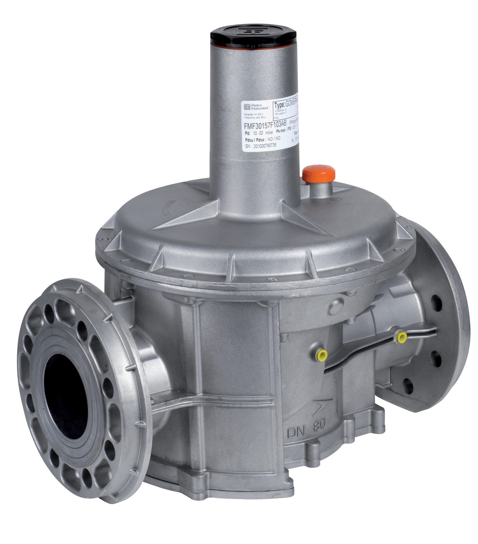
When testing flanged regulators such as the CBM Pressure regulator with flanges DN50 500 Mbar PS 5/300 Mbar or CBM Pressure regulator with DN65 flanges 500 Mbar PS 5/300 Mbar, isolate both upstream and downstream sections to differentiate between internal seal failure and connector leakage. This distinction prevents unnecessary component replacement and optimizes maintenance cost efficiency.
Visual Inspection Techniques
Conduct visual inspection using soap solution application to all valve body seams, threaded connections, and packing gland regions. Mix 1 part liquid dish soap with 4 parts water in spray bottle, apply to suspect areas, and observe bubble formation indicating leakage paths. Photograph leakage locations for maintenance records and trending analysis.
Examine valve body exterior for corrosion staining, mineral deposits, or discoloration patterns that indicate previous leakage or environmental stress. Pay particular attention to valve outlet areas where mineral deposits accumulate from micro-leakage over extended operating periods. These deposits serve as visual early-warning indicators of seal degradation before catastrophic failure occurs.
For pilot light applications using the CBM 1-flame pilot light 0.150.082, inspect flame color and stability as secondary indicators of gas delivery integrity. Blue flame indicates complete combustion with adequate gas flow, while yellow or orange flame suggests incomplete combustion from reduced pressure or contaminated gas delivery.
Ultrasonic Leak Detection
Ulrasonic acoustic monitoring detects high-frequency sound waves (20-100 kHz) generated by gas escaping through seal failures, enabling non-contact leakage detection invisible to visual inspection. Ultrasonic detectors identify micro-leakage before pressure decay becomes measurable through conventional testing, extending equipment service life by enabling seal replacement during planned maintenance windows.
This technology proves particularly valuable for large flanged regulators where internal leakage detection requires time-consuming isolation procedures. Deploy ultrasonic inspection monthly during preventive maintenance routines, establishing baseline acoustic signatures for trending analysis and predictive maintenance scheduling.
Root Cause Analysis Framework for Seal Failures
Installation and Torque Specification Errors
Incorrect flange bolt torque represents the most frequent cause of seal failure in flanged gas regulators. Over-torquing (>120% of specification) concentrates stress on seal material, accelerating creep and material failure. Under-torquing (<80% of specification) prevents adequate seal compression, resulting in immediate leakage upon pressure application.
For the CBM Pressure regulator with flanges DN50 500 Mbar PS 5/300 Mbar and CBM Pressure regulator with DN65 flanges 500 Mbar PS 5/300 Mbar, torque specifications range from 45-65 Nm depending on flange size and seal material composition. Always use calibrated torque wrenches and apply torque in progressive three-step sequences (30%, 70%, 100%) using diagonal bolt patterns. Document torque values in maintenance records for reference during future inspection cycles.
Temperature cycling during installation creates thermal stress concentrations when bolts are tightened under ambient conditions then exposed to operational temperatures. Allow regulators to stabilize at operating temperature before final torque verification, then re-torque connections after 4-8 hours of continuous operation to compensate for thermal expansion and material settling.
Material Incompatibility with Gas Media
Sealing materials must demonstrate chemical compatibility with pressurized gas composition. Standard elastomer seals (Buna-N, EPDM) function appropriately for natural gas applications but fail rapidly when exposed to corrosive gases such as hydrogen sulfide, ammonia, or chlorine compounds. Verify gas composition analysis before regulator selection and specify seal materials accordingly.
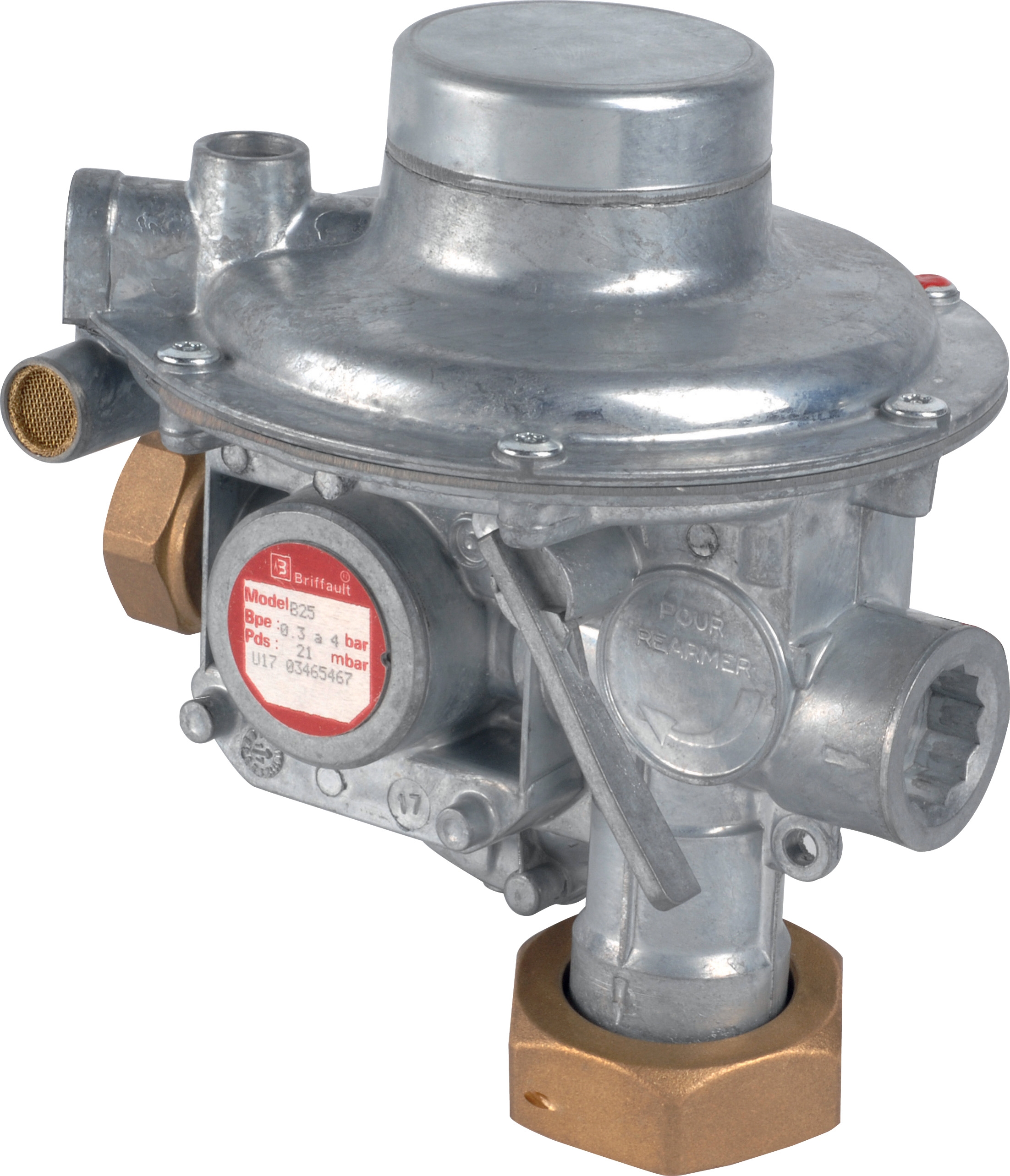
The CBM Regulator Francel B10/37mbar with safety requires particular attention to seal material specification given its typical application in safety-critical pilot light circuits. Always confirm that replacement seals match original specification rather than substituting commonly available alternatives that may lack chemical compatibility with installed gas media.
Moisture ingress accelerates chemical degradation through hydrolysis of sealing materials, particularly in applications with condensation potential. Implement moisture separation equipment upstream of regulators, establish drain maintenance schedules for water accumulation removal, and monitor inlet air quality compliance with ISO 8573-1 Class 6 or better.
Cyclic Pressure Fatigue
Repetitive pressure cycling induces fatigue cracking in seal materials and valve body structures, particularly at stress concentration points near ports and seal cavities. Applications with frequent pressure swings (>50 cycles daily) demonstrate accelerated seal degradation compared to stable-pressure operations.
Establish predictive replacement intervals based on measured cycle counts and historical failure data for your specific gas composition and pressure range. Deploy pressure data loggers upstream of critical regulators to quantify actual pressure cycling rates, then adjust maintenance schedules accordingly. This data-driven approach prevents premature component removal while optimizing safety margins.
Preventive Maintenance Protocols and Component Specifications
Scheduled Inspection Intervals
Develop maintenance scheduling based on application criticality, operating hours, and historical failure data. Critical applications warrant quarterly inspection cycles consisting of pressure decay testing, visual soap solution inspection, and photographic documentation of regulator condition.
Non-critical applications with stable operating conditions may extend inspection intervals to semi-annual schedules, provided that pressure decay testing consistently demonstrates leak rates below 1% per hour. Immediately reduce inspection intervals to monthly cycles if any single test reveals leakage exceeding 2% per hour.
For threaded regulators such as the CBM Pressure regulator threaded D1"1/2 500 Mbar PS 5/300 Mbar, incorporate thread inspection into visual assessment procedures, checking for corrosion, thread damage, or sealant compound degradation. Re-thread with appropriate gas-rated sealant tape or compounds every 24 months to maintain connection integrity.
Seal Replacement Best Practices
When seal replacement becomes necessary, drain system pressure completely before disassembly, isolate the affected valve section using upstream and downstream isolation blocks, and allow internal pressure equalization before opening connections. This procedure prevents sudden pressure release that could project seal fragments or damage internal seat geometry.
Document original seal specification, material composition, and installation date before removal. Photograph seal condition during disassembly to support root cause analysis and inform future preventive maintenance strategies. Preserve failed seals for laboratory analysis when failure modes appear inconsistent with normal degradation patterns.
Install replacement seals using manufacturer-recommended procedures, typically requiring specific installation tools to prevent cross-threading or material damage. Apply recommended thread sealant (PTFE tape or anaerobic compound) consistently without excessive application that could occlude internal passages. Perform hydrostatic test on the regulator at 1.5× maximum operating pressure before returning to service to verify installation integrity.
Spare Parts Planning and Inventory Management
Maintain minimum inventory of replacement seals, packing gland components, and gaskets for all critical regulators, established through failure analysis of 24-month historical records. Stock spare seals in sealed packaging stored in temperature-controlled environments (15-25°C) to prevent material degradation before installation.
For applications utilizing multiple regulator types, consolidate spare parts inventory on commonly specified models including the CBM Pressure regulator with flanges DN50 500 Mbar PS 5/300 Mbar and CBM Pressure regulator with DN65 flanges 500 Mbar PS 5/300 Mbar, which serve broad industrial applications across multiple facilities.
Establish spare parts procurement processes with lead time sufficient to accommodate planned seal replacements during scheduled maintenance windows, avoiding emergency purchasing costs and supply chain delays. Coordinate with 3G Electric's experienced technical team to establish customized spare parts recommendations aligned with your specific facility requirements and regulatory compliance obligations.
Troubleshooting Decision Tree and Remediation Procedures
Symptomatic Presentation: Gradual Pressure Loss
When downstream pressure declines gradually over periods of hours or days despite stable upstream supply, perform pressure decay testing to confirm regulator internal leakage. Document decay rate and compare against baseline performance benchmarks. If decay exceeds 2% per hour, the regulator seat or seal requires inspection and likely replacement.
Before assuming regulator failure, verify that apparent pressure loss does not originate from downstream system leakage through isolation testing. Close all downstream isolation valves and repeat pressure decay testing. If decay persists with downstream isolated, proceed with regulator seal inspection. If decay stops, direct troubleshooting toward downstream equipment.
Symptomatic Presentation: Sudden Pressure Instability
Unexpected pressure fluctuations with stable upstream conditions indicate regulator diaphragm failure or internal spring weakness permitting excessive seat movement. These failures typically develop rapidly, progressing from slight instability to complete loss of pressure control within hours.
Initiate emergency isolation of the affected regulator and inspect internal components including diaphragm condition and spring preload. Replacement typically requires regulator swap from spare equipment, as field repair of internal mechanisms risks seal re-installation errors. Return failed regulator to authorized service centers for complete reconditioning before return to spare equipment rotation.
Symptomatic Presentation: External Weeping at Connections
Visible liquid or vapor leakage at flange connections, threaded ports, or packing gland areas requires immediate isolation and visual inspection. Apply soap solution to confirm leakage location and severity, then determine whether tightening existing connections or seal replacement is appropriate.
If leakage originates from bolt connections, progressively tighten bolts in diagonal pattern by 1/4-turn increments without exceeding manufacturer torque specifications. Retest with soap solution after each increment. If leakage persists despite proper torque application, the seal has degraded and requires replacement.
For packing gland leakage at threaded connections, apply 1-2 layers of PTFE tape over existing threads and re-thread the connection, gradually increasing pressure during startup to verify seal integrity. If weeping continues, disconnect and replace the packing gland assembly completely.
Weeping from flanged connections that persists after torque correction requires flange separation, seal inspection, and seal replacement using the procedures outlined in Seal Replacement Best Practices section. Never exceed recommended torque values attempting to stop leakage through excessive bolt tightening, as this accelerates seal degradation and may damage regulator body threads or flanges.