Understanding Gas Valve Regulation Fundamentals
Gas Valves & Regulation form the backbone of industrial process control, yet many facility operators lack a complete understanding of how these systems actually function under dynamic conditions. Unlike simple on-off valve operation, pressure regulation involves complex interactions between inlet pressure, downstream demand, and regulator characteristics. When pressure fluctuates upstream—common in industrial settings with multiple consumers—regulators must respond instantly to maintain setpoint stability.
The fundamental principle behind regulation is negative feedback: as downstream pressure rises toward setpoint, the regulator restricts flow; as demand increases and pressure drops, the regulator opens to restore equilibrium. This self-modulating behavior eliminates the need for constant manual adjustment, but only when the regulator is properly sized and configured for your specific application.
With over 35 years of experience supplying industrial equipment across Asia-Pacific, 3G Electric has observed recurring issues stem from mismatched regulator selections. Undersized regulators cannot handle peak flow demands and exhibit "hunting"—rapid pressure oscillations that compromise process stability. Oversized regulators respond too slowly to pressure changes, creating lag that destabilizes downstream equipment.
Understanding your regulator's control authority—its ability to maintain setpoint across varying inlet pressures and flow rates—is critical. Most industrial regulators operate effectively within a ±10% inlet pressure range, meaning if your supply pressure varies beyond this, you may need a two-stage regulation system with pilot-operated valves.
Multi-Stage Pressure Regulation and Cascaded Control
Complex industrial processes frequently demand multi-stage regulation to achieve stable, precise outlet pressures across wide operating ranges. This approach involves positioning multiple regulators in series, each handling a portion of the total pressure drop while maintaining independent setpoint control.
A typical two-stage system operates as follows: the first-stage regulator (called the "main regulator") reduces high inlet pressure to an intermediate pressure—typically 5-10 bar higher than the final setpoint. The second-stage regulator then performs fine pressure adjustment from this intermediate level to the final process pressure. This division of labor provides several advantages:
Improved Regulation Quality: Each regulator handles a smaller pressure differential, enhancing its ability to respond to demand changes. A regulator designed to drop 50 bar will respond more quickly and precisely than one dropping 100 bar.
Reduced Heat Generation: Large pressure drops generate heat through fluid throttling, which can damage sensitive components or alter gas properties. Dividing the drop across two stages dissipates heat more evenly.
Extended Valve Life: Lower differential pressures reduce mechanical stress on valve seats and springs, extending service intervals significantly.
Pilot-Operated Architecture: In demanding applications, consider using a pilot-operated regulator for the second stage. These regulators use a small amount of controlled outlet pressure to modulate a larger main valve, delivering superior pressure stability and minimal droop (pressure decrease under no-flow conditions). The Francel B25/37mb pressure regulator with integrated safety relief exemplifies this design, delivering stable 37 mbar outlet pressure for laboratory and industrial gas distribution requiring both primary regulation and overpressure protection.
When implementing multi-stage systems, ensure the first-stage outlet pressure exceeds the second-stage setpoint by at least 2 bar to maintain proper pilot signal integrity. Mount each regulator on independent manifold blocks to isolate thermal effects and vibration coupling.
Flow Capacity Matching and Pressure Drop Calculations
One of the most common commissioning errors occurs when technicians fail to match regulator flow capacity to actual system demand. Every regulator specification sheet lists a maximum flow rating, typically measured at specific inlet pressure and outlet pressure differential conditions. Using a regulator at excessive flow creates permanent pressure drop—the outlet pressure falls below setpoint even with the valve fully opened.
Calculate your system's required flow capacity using this practical approach:
Step 1: Identify Peak Consumption Points
Map all downstream consumers and document their simultaneous flow requirements. For example, if you operate three burners, each consuming 50 m³/h, your simultaneous demand could reach 150 m³/h when all three operate together. Many engineers mistakenly use "nameplate" ratings that assume sequential rather than simultaneous operation.
Step 2: Apply Safety Margin
Add 20-30% to your calculated peak flow to accommodate future expansion and account for measurement uncertainties. A system designed for exactly 150 m³/h will have zero regulation margin when flow reaches 150 m³/h.
Step 3: Select Regulator with Adequate Capacity
Choose a regulator rated for at least 150 × 1.25 = 187.5 m³/h at your operating pressure. The Pratissoli R1/400 regulating valve rated for 110 L/min (6.6 m³/h) flow capacity suits high-pressure pump systems maintaining precise control in KE, EV, and KT-series pump installations, providing stable regulation within its designed performance envelope.
Step 4: Verify Outlet Pressure Stability
After installation, measure outlet pressure at minimum flow (5-10% of rated capacity) and maximum flow. Acceptable droop should not exceed 5% of setpoint. If pressure drop exceeds this, your regulator is oversized or inlet pressure is insufficient.
For applications involving multiple endpoints at different distances from the regulator, calculate pressure drop in downstream piping using standard hydraulic formulas. A 20 mm copper line carrying 100 m³/h at 4 bar loses approximately 0.3 bar per 100 meters of length. Compensate by increasing regulator setpoint slightly, or install secondary regulators at remote endpoints.
Specialized Applications: High-Pressure and End-of-Stroke Control
Industrial facilities occasionally encounter specialized regulation challenges that generic solutions cannot adequately address. High-pressure applications—such as hydraulic pump systems requiring 300+ bar outlet pressure—demand regulators engineered specifically for extreme service. The Pratissoli R1/400 regulating valve is rated to 400 bar with 110 L/min flow capacity, providing stable pressure control in high-performance hydraulic systems while maintaining system stability across full operating range.
For pneumatic and gas control systems requiring end-of-stroke functionality, the Elektrogas VMM 20-25 end-of-stroke contact gas valve rated for 6 bar pressure and designed to EN 161 standard addresses a specific control requirement: detecting when an actuator reaches its mechanical limit and triggering a control signal. This valve incorporates an electrical contact that closes when gas pressure reaches the setpoint (6 bar in this design), enabling automated shutdown sequences or status indication. Adjustment requires a 3 mm Allen wrench for field calibration.
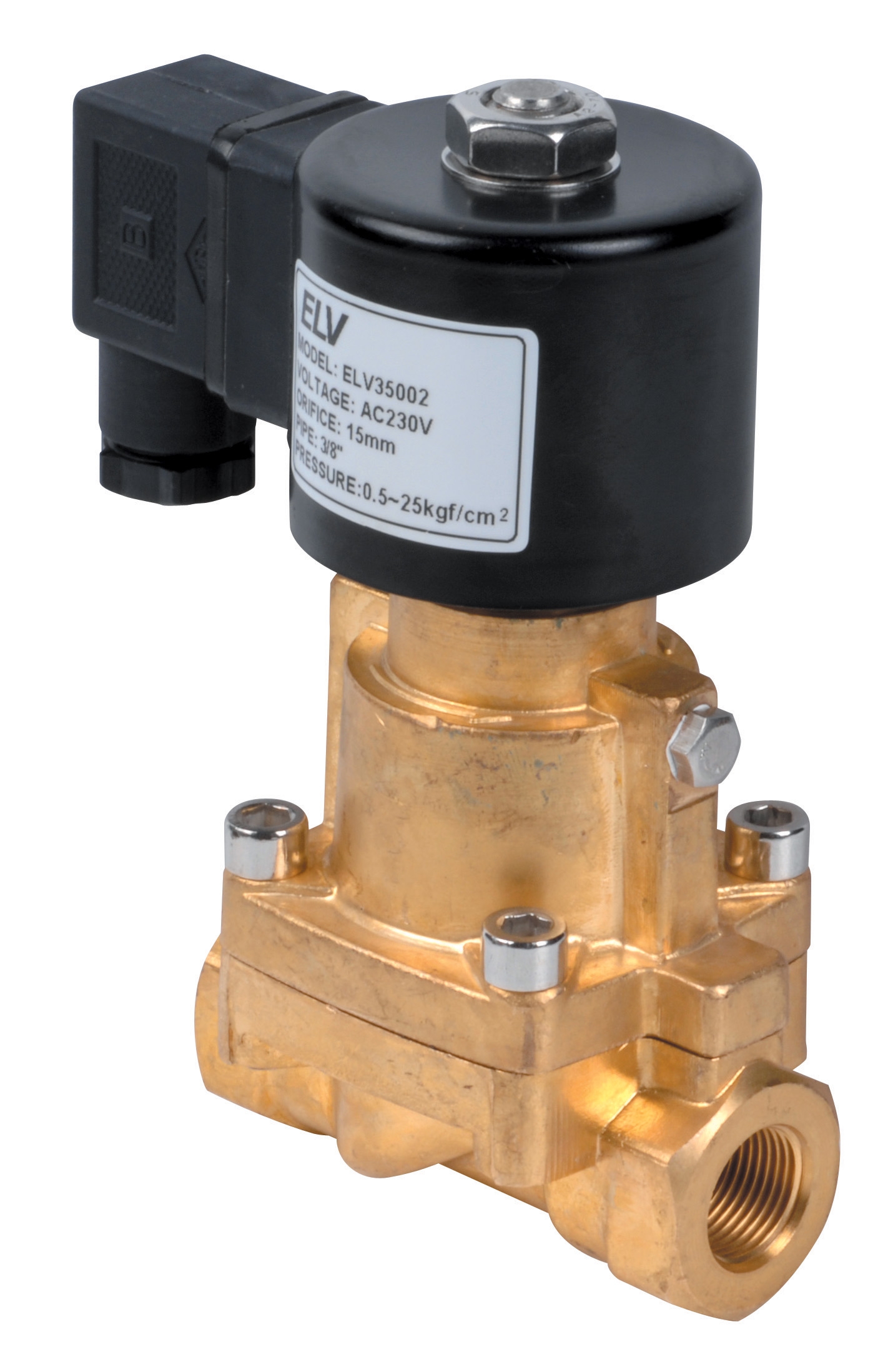
Steam regulation presents unique challenges because steam properties change rapidly with pressure and temperature. The ELV steam solenoid valve DN 1/2 rated for 0.5–10 bar operating pressure with 25 bar maximum differential pressure and 4.5 Cv flow coefficient handles steam flow control in industrial heating and process applications. Steam regulators must accommodate two-phase flow (liquid water droplets within steam vapor), which causes erosion and wire-drawing of valve seats if not properly designed. Ensure steam supply passes through a quality steam trap upstream of any regulator to remove condensate.
For high-pressure hose assemblies requiring durable flow control components, the Pratissoli ZT06B1000353 high-pressure sewer cleaning hose assembly incorporates Italian-engineered valve technology suitable for demanding industrial applications delivering complete hose solutions with integrated fittings and control components.
Practical Installation and Testing Procedures
Proper installation determines whether your gas regulation system achieves its design performance or underperforms throughout its service life. Begin with a clean, isolated installation: depressurize the system completely, and flush piping with nitrogen or process gas to remove manufacturing debris, welding spatter, and accumulated dirt. Particle contamination is the leading cause of regulator malfunction in industrial systems.
Mount regulators on vertical pipe sections whenever possible, with the inlet connection at the bottom. This orientation prevents liquid slugs (water droplets in natural gas, or oil in compressed air systems) from collecting inside the regulator body. If space constraints require horizontal mounting, install a small settlement chamber immediately upstream with a drain valve to trap condensate.
Connect a pressure gauge (0-10 bar range for low-pressure systems, 0-250 bar for high-pressure) immediately downstream of the regulator, and a second gauge on the outlet side. Never trust the integral gauge if pressure regulation seems abnormal—it may be internally damaged while appearing functional. Many technicians misdiagnose regulator failure when the actual problem is a defective internal gauge.
Before pressurizing, verify that the regulator adjustment screw is backed out 2-3 complete rotations from the seated position. Applying pressure to a fully seated regulator can damage the pilot valve and create safety hazards. Gradually increase inlet pressure while observing outlet pressure response. The outlet pressure should rise smoothly and stabilize at approximately 0.5 bar below the regulator's setpoint due to natural droop under zero-flow conditions.
Adjust the regulator setpoint by rotating the adjustment screw clockwise to increase pressure or counterclockwise to decrease it. One complete rotation typically produces a 0.5-1.0 bar change, depending on regulator design. Make small adjustments (quarter-turn increments) and allow 30 seconds for the system to stabilize before reading the gauge. This patience prevents overshooting and prevents unnecessary pressure cycling.
Conduct a flow test by opening downstream isolation valves gradually while monitoring outlet pressure. Stable pressure under varying flow rates confirms the regulator is properly sized and functioning correctly. If pressure drops significantly with increasing flow (more than 5% variation), the regulator is undersized or the inlet pressure is inadequate.
Maintenance and Troubleshooting in Industrial Environments
Industrial gas regulation systems require preventive maintenance schedules aligned with application severity and environmental conditions. Facilities with heavily contaminated intake air (near coastal areas, industrial zones, or high-traffic locations) should inspect regulators quarterly. Cleaner environments may extend inspection intervals to annually.
During scheduled maintenance, perform a visual inspection for corrosion, cracks in gauge glass (if fitted), and visible leakage around the adjustment screw stem. Check that all fasteners remain tight—vibration can gradually loosen mounting bolts and valve fittings. Test the regulator's ability to hold setpoint by closing downstream isolation valves and observing outlet pressure over 5 minutes. An increase of more than 0.2 bar during this time indicates internal leakage that requires professional servicing.
Common troubleshooting issues include hunting (rapid pressure cycling), inability to maintain setpoint, and excessive noise. Hunting typically results from undersizing—the regulator opens and closes repeatedly as it overcompensates for demand changes. Install a slightly larger regulator or implement a secondary downstream filter-regulator to dampen pressure fluctuations. If these measures fail, the system may require a pilot-operated regulator with better control stability.
Inability to reach setpoint indicates insufficient inlet pressure or internal obstruction. Verify inlet pressure by measuring directly at the regulator inlet. Most regulators require inlet pressure at least 2-3 bar above the setpoint to function properly. If inlet pressure is adequate, the internal pilot seat may be damaged by particle contamination, necessitating professional overhaul.
Excessive noise—particularly hissing or whistling—suggests oversized regulator or extremely low inlet pressure. Both conditions force the regulator to operate near its fully-closed position, where high-velocity gas creates noise. Verify the application truly demands the current setpoint; sometimes reducing setpoint by 0.5 bar eliminates noise while still meeting process requirements.
With 3G Electric's extensive experience supporting industrial operations across Singapore and Southeast Asia, we recommend establishing a spare regulator inventory for critical applications. This allows rapid replacement while the failed unit undergoes professional servicing, minimizing production downtime. Document setpoint configurations in your maintenance records so replacement regulators can be pre-adjusted before installation.
Conclusion and System Optimization
Effective Gas Valves & Regulation requires understanding both theoretical principles and practical implementation realities. By properly sizing regulators to your peak demand, implementing multi-stage control for complex applications, and maintaining consistent preventive maintenance, you create a regulation system that delivers stable, safe pressure control throughout your industrial facility's operational life.
The choice of regulator profoundly impacts system performance. Whether you require basic pressure reduction with safety relief like the Francel B25/37mb, precision control in high-pressure pump systems like the Pratissoli R1/400, specialized end-of-stroke detection like the Elektrogas VMM 20-25, or steam control capabilities like the ELV steam solenoid valve, selecting equipment engineered for your specific conditions ensures optimal performance.
Industrial professionals working with gas systems should regularly review their regulation system design against evolving operational demands. As your facility grows or production processes change, yesterday's "correctly sized" regulator may become inadequate. Periodic pressure testing, flow verification, and comparative analysis against current system requirements identify optimization opportunities before problems develop.
3G Electric remains committed to providing industrial professionals with quality equipment and technical support for gas regulation challenges across all industrial sectors. Contact our technical team to discuss your specific pressure control requirements and receive recommendations for optimized system design.